Paragraphs 4-6
KUBOTA
^
11
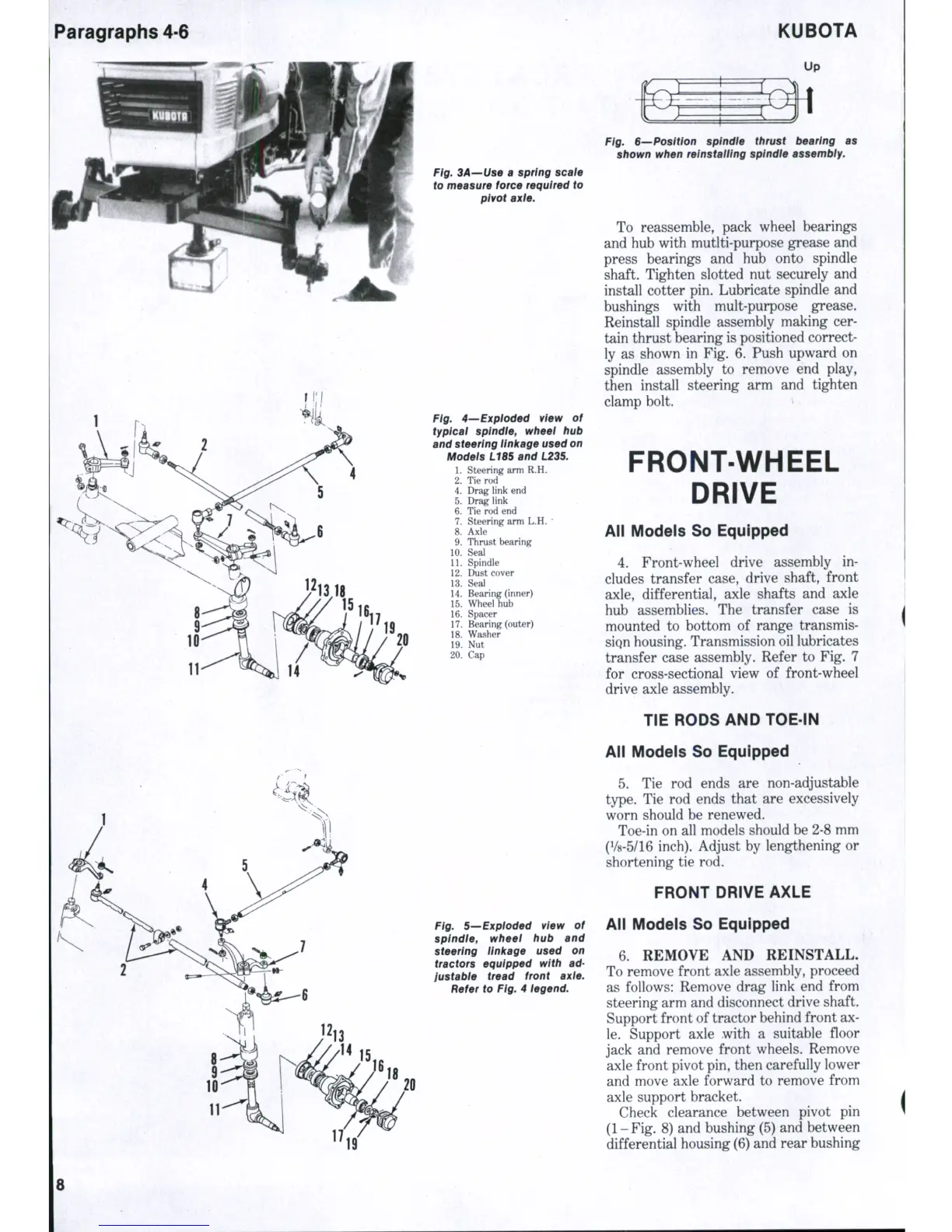
Fig. BA—Use a spring scafe
to measure force required to
pivot axie.
Fig. 4—'Expioded view of
typicai spindie, wheei hub
and steering iinkage used on
Modeis L18S and L23S.
1.
Steering arm R.H.
2.
Tie rod
4.
Drag link end
5.
Drag link
6. Tie rod end
7.
Steering arm L.H.
*
8. Axle
9. Thrust bearing
10.
Seal
11.
Spindle ,
12.
Dust cover
13.
Seal
14.
Bearing (inner)
15.
Wheel hub
16.
Spacer
17.
Bearing (outer)
18.
Washer
19.
Nut
20.
Cap
Fig. 5—Expioded view of
splndie, wheei hub and
steering ilni(age used on
tractors equipped with ad-
justabie tread front axie.
Refer to Fig. 4 iegend.
Fig. S—Position spindie thrust bearing as
shown when reinstaiiing spindie assembiy.
To reassemble, pack wheel bearings
and hub with mutlti-purpose grease and
press bearings and hub onto spindle
shaft. Tighten slotted nut securely and
install cotter pin. Lubricate spindle and
bushings with mult-purpose grease.
Reinstall spindle assembly making cer-
tain thrust bearing is positioned correct-
ly as shown in Fig. 6. Push upward on
spindle assembly to remove end play,
then install steering arm and tighten
clamp bolt. >
FRONT-WHEEL
DRIVE
All Models So Equipped
4.
Front-wheel drive assembly in-
cludes transfer case, drive shaft, front
axle,
differential, axle shafts and axle
hub assemblies. The transfer case is
mounted to bottom of range transmis-
siQn housing. Transmission oil lubricates
transfer case assembly. Refer to Fig. 7
for cross-sectional view of front-wheel
drive axle assembly.
TIE RODS AND TOE-IN
All Models So Equipped
5.
Tie rod ends are non-adjustable
type.
Tie rod ends that are excessively
worn should be renewed.
Toe-in on all models should be 2-8 mm
(1/8-5/16 inch). Adjust by lengthening or
shortening tie rod.
FRONT DRIVE AXLE
All Models So Equipped
6. REMOVE AND REINSTALL.
To remove front axle assembly, proceed
as follows: Remove drag link end from
steering arm and disconnect drive shaft.
Support front of tractor behind front ax-
le.
Support axle with a suitable floor
jack and remove front wheels. Remove
axle front pivot pin, then carefully lower
and move axle forward to remove from
axle support bracket.
Check clearance between pivot pin
(1-Fig. 8) and bushing (5) and between
differential housing (6) and rear bushing
 Loading...


