TIRE
INFLATION
Ensure
that
the
tractor tires
are
properly inflated.
Refer
to
the
tractor
operator's
manual
for optional tires.
•Inflation
pressure
Tire
sizes
Inflation
Pressure
9.5-16,
4PR
140kPa(1.4kgf/cm^ 20psi)
11.2-16,4PR
130kPa(1.3kgf/cm^ 18psi)
Rear
12-
16.5,4PR
270kPa(2.7kgf/cm^ 40psi)
31x15.5-15,
4PR
140kPa(1.4kgf/cm^ 20psi)
33x12.5-15,
4PR
140kPa{1.4kgf/cm', 20psi)
6-12,
4PR
200kPa(2.0kgf/cm^ 28psi)
7-12,
4PR
170kPa(1.7kgf/cm^ 24psi)
Front
21x8.00-10,
4PR
160kPa(1.6kgf/cm', 23psi)
23x8.50-12Turf,
4PR
150kPa(1.5kgf/cm^ 22psi)
23x8.50-12lnd..4PR
250kPa(2.5kgf/cm^ 35psi)
TEST
OPERATION
A
WARNING
To
avoid
serious
personal
injury:
Keep
engine
speed
at
low
idle
during
the
test
operation.
Escaping
hydraulic
fluid
under
pressure
can
have
sufficient
force
to
penetrate
skin,
causing
serious
personal
Injury.
Before
disconnecting
lines,
be
sure
to
relieve
all
pressure
by
moving
the
controls.
Before
applying
pressure
to
the
system,
be
sure
ail
connections
are
tight
and
that
lines,
tubes
and
hoses
are
not
damaged.
Fluid
escaping
from
a
very
small
hole
can
be
almost
Invisible.
Use
a
piece
of
cardboard
or
wood,
rather
than
your
hands
to
search
for
suspected
leaks.
If
injured
by
escaping
fluid,
see
a
doctor
at
once.
Serious
infection
or
allergic
reaction
will
develop
If
proper
medical
treatment
is
not
administered
immediately.
PRE-OPERATION
CHECK
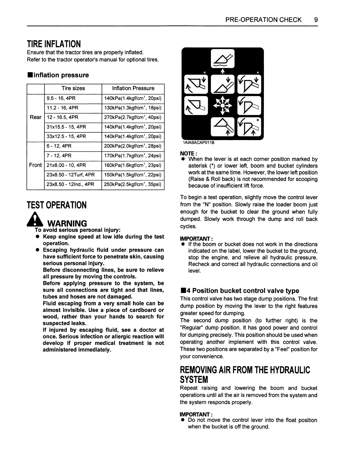
1AIABACAP011B
NOTE:
•
When
the
lever is
at
each
comer
position
marked
by
asterisk (*) or lower left, boom
and
bucket cylinders
work
at
the
same
time. However,
the
lower left position
(Raise
& Roll back) is not
recommended
for
scooping
because
of
insufficient
lift
force.
To begin a
test
operation, slightly
move
the
control lever
from the "N" position. Slowly raise the loader boom just
enough
for
the
bucket to
clear
the
ground when fully
dumped.
Slowly work through
the
dump
and
roll
back
cycles.
IMPORTANT:
• If
the
boom
or
bucket
does
not
work
in
the
directions
indicated on
the
label, lower
the
bucket
to
the
ground,
stop
the
engine,
and
relieve all hydraulic
pressure.
Recheck
and
correct
all hydraulic
connections
and
oil
level.
•4
Position
bucket
control
valve
type
This control valve
has
two
stage
dump
positions.
The
first
dump position by moving
the
lever to
the
right
features
greater
speed
for dumping.
The
second
dump
position (to further right) is
the
"Regular"
dump
position. It
has
good
power
and
control
for dumping precisely. This position
should
be
used
when
operating
another
implement
with
this
control valve.
These
two positions
are
separated
by a "Feel" position for
your
convenience.
REMOVING
AIR
FROM
THE
HYDRAULIC
SYSTEM
Repeat
raising
and
lowering
the
boom
and
bucket
operations
until all
the
air is
removed
from
the
system
and
the
system
responds
properly.
IMPORTANT:
• Do not move
the
control lever into
the
float position
when
the
bucket
is off
the
ground.
 Loading...