15. ELECTRICAL EQUIPMENT
5
LIKE 50/125
PERFORMANCE TEST
Warm up the engine.
Remove the floor mat and front tool box
cover.
Stop the engine and open the fuse box.
Disconnect the wire lead from the fuse
terminal. Connect an ammeter between
the wire lead and fuse terminal as shown.
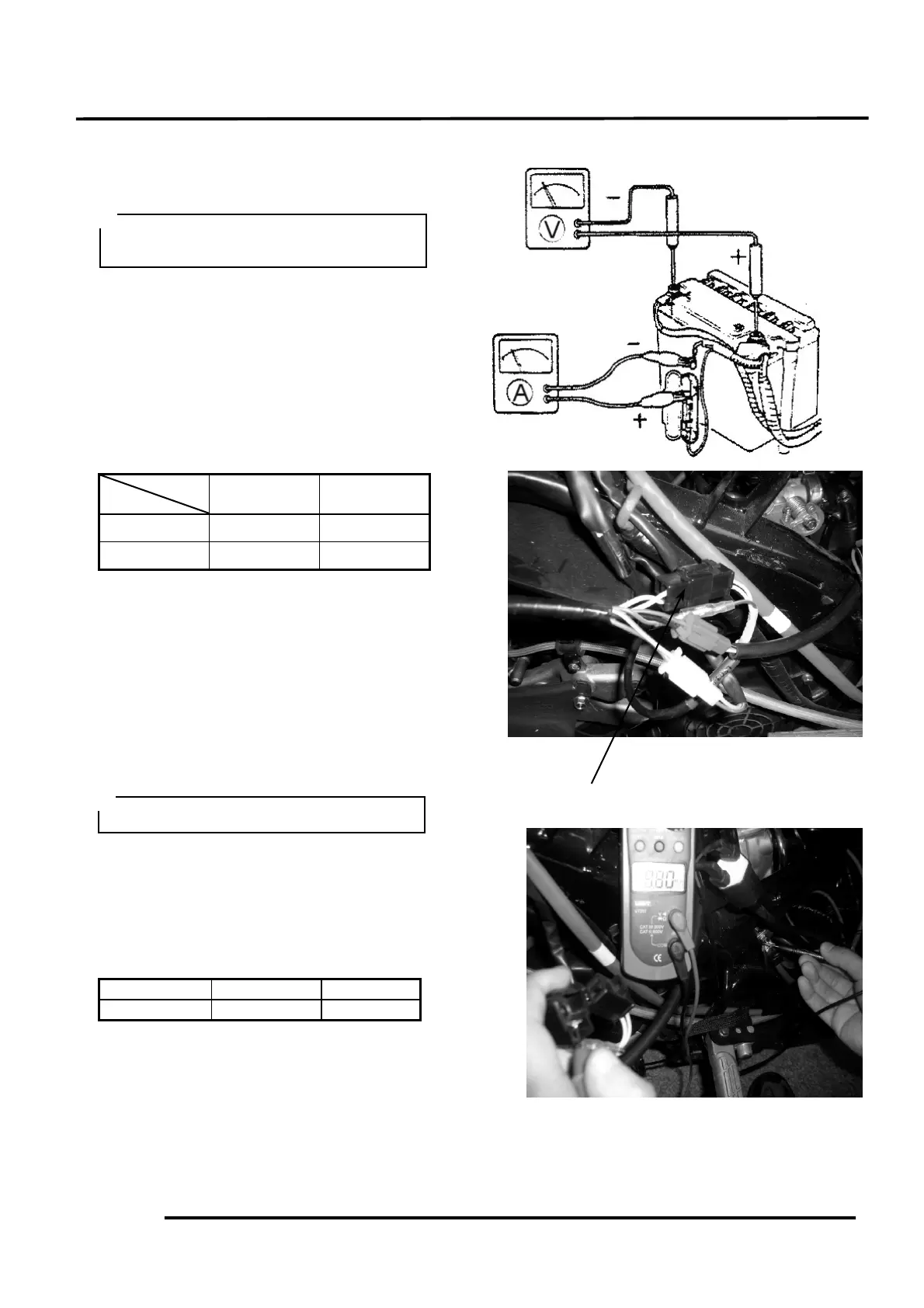
Connect the battery positive (+) terminal to
the voltmeter positive (+) probe and battery
negative (-) terminal to the voltmeter
negative (-) probe.
Start the engine, gradually increase engine
speed to test the output:
Position
RPM
Day Night
2500 1.3A min. 1.0A min.
6000 2.0A min. 2.0A min.
Charging Limit Voltage: 14.5±0.5V/8000rpm
If the limit voltage is not within the specified
range, check the regulator/ rectifier.
A.C. GENERATOR (CHARGING COIL)
INSPECTION
Remove the met-in box. (
Ö
12)
Disconnect the A.C. generator connector.
Measure the resistances between the
charging coil terminals (white–green) and
lighting coil terminals (yellow–green).
Resistances:
Charging coil white–green 0.4~2Ω
Lighting coil yellow–green 0.3~2Ω
Refer to 7-3 for A.C. generator removal.
.C. Generator Connecto
Use a fully charged battery to check the
charging system output.
*
Inspect with the engine installed.
*
 Loading...