SerialInterface
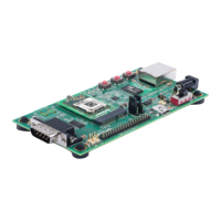
The evaluation kit has one RS232 port for connection to the xPico 200 internal UART.
Serial port 1 is a DB9M (DTE) connector labeled J6. The null modem cable can be used
to connect J6 directly to a standard PC RS232 serial port.
RS‐232SignalsonJ6SerialInterface
xPico 200 Evaluation Kit
Pin Function Serial Port
DB9M
Pin Number
TX_232 (Data Out) 3
RX_232 (Data In) 2
CTS_232 (HW Flow Control Input) 8
RTS_232 (HW Flow Control Output) 7
DTR_232 (Modem Control Output)
(Populate R56)
4
DCD_232 (Modem Control Input)
(Populate R57)
1
GND (Ground) 5
Note
The evaluation board is configured for RS232 on the UART signals. If attempting to use
the J2 UART TTL header pins instead of the RS232 transceiver, pin 22 of the serial
transceiver (U8) should be tied to ground.
EthernetInterface
The xPico 200 evaluation kit includes one RJ45 connector with on-board magnetics for
connection to the xPico 200 module 10/100Mbps Ethernet interface. Connector J3 is the
Ethernet port.

 Loading...