PowerSupply
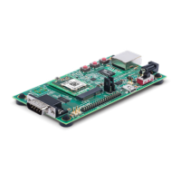
The evaluation kit provides multiple input Power Options. Included with the kit is a 5V
wall adapter which plugs into barrel connector J4. In addition to powering from the wall
adapter, the evaluation kit can be powered from a standard PC USB Host port by
connecting a USB cable between the PC and J9. If powered via USB, the unit must be
configured for USB device mode (JP3 pins 1 to 2, JP5 out, JP6 out).
PowerOptions
Input Power Option Description
5V Wall Cube Connect 5V wall cube to the J4 barrel connector.
USB (device mode,
power input)
Connect J9 USB power to a PC USB Host Port.
Note: For J9 Note unit must be configured for USB device mode
(JP3 pins 1 to 2, JP5 out, JP6 out.)
LEDs
The xPico evaluation kit includes several LEDs to communicate module, Ethernet activity,
or power status. The LED Signals table lists all LEDs and their functions.
LEDSignals
J7
Pin
LED Ref
Design
Color LED Function
6 LED1 Orange
xPico 200 Status
LED blinks with patterns indicating module status. See the
xPico 200 Series Embedded Wi-Fi Gateway User Guide for
a full description of the status LED blink patterns.
None LED2 Orange
Ethernet Link Status
LED is ON when there is a valid Ethernet link at 100 Mbps
None LED3 Orange
Ethernet Activity
LED blinks when there is activity on the Ethernet port
 Loading...