08
3
A1
A2
2.
1.
A3
A2
A2
A1
4.
3.
A3
A2
<
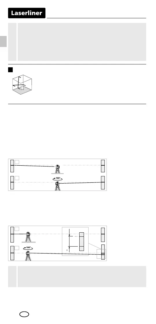
0,5 mm / m = OK
When A2 and A3 are more than 0.5 mm / m apart,
an adjustment is necessary. Contact your authorised dealer
or else the UMAREX-LASERLINER Service Department.
!
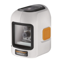
Performing the calibration check
3. Position the device as near as possible to the wall
at the height of point A1.
4. Turn the device through 180° and mark point A3.
The difference between points A2 and A3 is the tolerance.
1. Mark point A1 on the wall.
2. Turn the device through 180° and mark point A2.
You now have a horizontal reference between points A1 and A2.
Preparing the calibration check
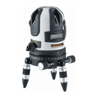
It is possible for you to check the calibration of the laser. To do this,
position the device midway between 2 walls, which must be at least
5 metres apart. Switch the device on (LASER CROSS ON). The best
calibration results are achieved if the device is mounted on a tripod.
Do not release transport restraint, push slide switch (3)
to the right. Sloping planes can now be measured.
This mode cannot be used to perform horizontal or
vertical levelling as the laser lines are no longer aligned
automatically. LED (1) and the laser lines ash red.
Slope mode
The transport restraint must be released for horizontal and
vertical levelling. The LED (1) shows a permanent red light.
The laser lines flash as soon as the device is outside the
automatic levelling range of 4°. Position the device such
that it is within the levelling range. The light of the laser lines
is constant again.
!
EN
 Loading...