Catalog Numbers • Les Numéros de Catalogue • Números de Catálogo: PW-311
Country of Origin: Made in China • Pays d’origine: Fabriqué en Chine • País de origen: Hecho en China
PW-311-U is BAA and TAA compliant (Product produced in the U.S.)
Wattstopper
®
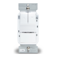
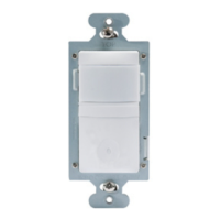
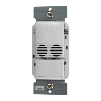
Passive Infrared 0–10 Volt Wall Switch Occupancy Sensor (Version 3)
Interrupteur mural 0–10 Volt avec détecteur de mouvement à infrarouges passif (v3)
Sensor de ocupación con interruptor de pared y tecnología de infrarrojo pasivo de
voltaje 0 a 10 (v3)
Installation Instructions • Instructions d’Installation • Instrucciones de Instalación
No: 29109 – 10/21 rev. 2
INSTALLATION
1. Make sure that the power has been turned OFF at the circuit breaker.
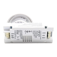
2. Connect wires to the PW flying leads as shown in the wiring diagram that
is appropriate to the PW model and electrical supply. The ground wire
(green) must be fastened to ground for the sensor to work properly.
3. Attach the sensor to the wall box by inserting screws into the two wide
holes on the top and bottom of the attached metal bracket. Match them up with the
holes in the wall box and tighten. Do not use excessive force when installing the
sensor into the wallbox. Doing so can bend the mounting strap which can affect
button operation.
4. Turn the circuit breaker ON. Wait one minute, then push the Auto ON/OFF switch
and the lights will turn ON. There is a delay due to initial power-up of the sensor that
only occurs during installation.
5. Test and adjust the sensor if necessary.
6. Install industry standard decorator wall switch cover plate (not included).
WARNING: Grounding the purple and pink wires can damage the unit. Do not apply power
to the sensor until all wires are connected or capped off if the driver is to be installed at a future time.
Signal Wire (Blue with White Stripe) connects to Neutral. For a replacement or retrofit application , it can connect to Ground.
NOTE: : Per UL, the 0-10V negative dimming wire color has been changed from gray to pink.
DESCRIPTION
The PW Passive Infrared Wall Switch sensors use advanced passive infrared (PIR) technology.
• PW sensors have Multi-Way available on all models.
• A “walk-through” mode can turn lights off after only 3 minutes, if no activity is detected after 30 seconds following an occupancy
detection.
• The PW-311 has one relay with dimming control capability and two buttons to allow control of the dimming.
• PW sensors contain a light level sensor. If adequate daylight is present, the sensor holds the load OFF until light levels drop, even
if the area is occupied. See the Light Level Adjustment section.
• On loss of normal power to the PW-311, the 0-10V dimming control will open. Any light fed with a separate circuit but controlled by
the unit’s 0-10V signal will go to 100%.
WARNING: TURN THE POWER OFF AT
THE CIRCUIT BREAKER BEFORE WIRING.
SPECIFICATIONS
Voltages ...................................................... 120/240/277 VAC, 50/60 Hz
Load Limits:
@120 VAC ........... 1000-W tungsten ballast, E-ballast, LED, 1/4 HP
@240/277 VAC ............... 1200-W ballast, E-ballast, LED, 1/4 HP
Time Delay Adjustment ..................................................3 to 30 minutes
Walk-Through Mode ....................... 3 minutes if no activity after 30 sec.
Test Mode ............................................. 10 min. with 10-sec. time delay
PIR Adjustment .................................................................... High or Low
Light Level Adjustment .......................................................8fc to 180+fc
Alerts ........................................................Selectable Audible & Visual
Terminal screw torque ............................................ 16 lbf-in (18 kgf-cm)
High Trim .................................................................................. 6 to 10 V
Low Trim .....................................................................................0 to 4 V
Ramp Up .......................................................................1 to 10 seconds
Fade Down ................................................................. 2.5 to 30 seconds
Signal Wire, Multi-Way Capability
Complementary Listed to “Emergency Lighting Equipment”, (UL924)
Driver
or Ballast
Red
Black
Line
Green
Signal
(Blue w/
White
Stripe)
Ground
Purple
Yellow
Pink
Dimming