J J
J J
J
66
66
6
Supply CheckSupply Check
Supply CheckSupply Check
Supply Check
➭ Remove the transformer secondary fuses (located on SUPPLY board), set
the Variac to the nominal mains voltage, check with the Multimeter the AC
supply voltages:
F1-F2=102±2Vac
F3-F4=60±1.5Vac.
➭ Re-set the Variac at zero voltage, turn off the amplifier and put the fuses back
on its holders.
➭ Connect the oscilloscope probe CH1 to the channel output, before RL1, set
it to 20V/div. 1mS/div.
➭ Set up the Variac slowly monitoring the Outputs with the oscilloscope CH1
connected, it should display the sinusoidal input signal amplified with no
distortions, if a distortion occur check the AMPLIFIER board as suggested in
the ADVICES section.
➭ If the protection trips, turn off the amplifier, wait some minutes and disconnect
the supplies from the amplifier module (CN2, CN3 on AMPLIFIER board),
continue to check the supplies.
➭ Finally verify the DC supplies on SUPPLY board:
CN2 pin 5 (+Vcc2) =+71±2Vdc
CN3 pin 1 (+Vcc1) =+42±1.5Vdc
CN3 pin 5-6 (-Vcc1) =-42±1.5Vdc
CN3 pin 4 (-Vcc2) =-71±2Vdc
CN2 pin 3 =+15±1Vdc
CN2 pin 2 =-15±1Vdc
➭ If one or more voltages don’t correspond, check the rectifiers, capacitors and
transformers disconnecting them from circuitry, refer to schematics.
Channels CheckChannels Check
Channels CheckChannels Check
Channels Check
➭ Verify, with the Multimeter, the insulation between the heatsink and the
transistors collectors.
➭ Verify, with the Multimeter, the PTC resistor value (R59), it must be between
50Ω and 200Ω.
➭
SETUP:SETUP:
SETUP:SETUP:
SETUP:
Connect the CH1 scope GND clip to CN2 pin 6 (SGND terminal).
Connect the CH1 probe tip to CN3 pin 2 or 3 (PWR out).
Connect the CH2 probe tip to D20 anode and set its sensitivity at 5V/div.
Set the LEVEL potentiometer full clockwise.
The load resistor is disconnected.
➭
INITIAL TEST:INITIAL TEST:
INITIAL TEST:INITIAL TEST:
INITIAL TEST:
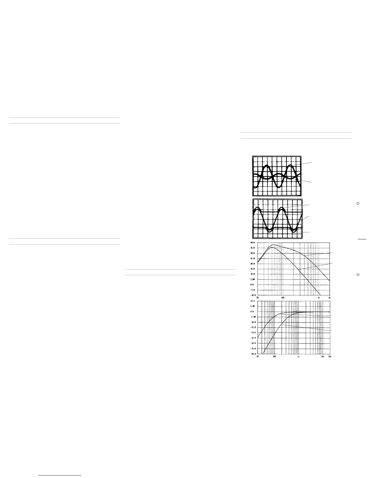
Increase slowly the Variac. The channel output signals must be symmetrical
respect the GND without visible distortion and oscillation as shown in
Fig.1
Trace A
(
Trace B
shown the amplifier 2nd stage input). If there is a distortion
read the section ADVICES.
➭
HIGH RAIL CHECK:HIGH RAIL CHECK:
HIGH RAIL CHECK:HIGH RAIL CHECK:
HIGH RAIL CHECK:
Connect the CH2 probe tip to D25 cathode and set its sensitivity at 20V/div.
When the output signal (Positive half-wave) is less than 34Vp the voltage on
D25 cathode must remain constant at 40V, when the output signal exceeds
40Vp the voltage must follow the output signal with 6V offset (see
Fig.2 Trace
B
), to check the negative high rail connect the probe to D26 anode (see
Fig.2
Trace C
).
➭ Connect the 4Ω 500W load on the output and repeat the INITIAL and HIGH
RAIL checks.
➭
GAIN ADJUSTMENT:GAIN ADJUSTMENT:
GAIN ADJUSTMENT:GAIN ADJUSTMENT:
GAIN ADJUSTMENT:
Set the generator level at -10dB (0,245V
RMS
), adjust the trimmer VR1 on
CONTROLS & CROSSOVER board to obtain an output level of 19Vp
(13.4V
RMS
).
➭ Re-set the generator level at 0dB (0,775V
RMS
),
➭
SIGN/COMP SENSOR CHECK:SIGN/COMP SENSOR CHECK:
SIGN/COMP SENSOR CHECK:SIGN/COMP SENSOR CHECK:
SIGN/COMP SENSOR CHECK:
Set the LEVEL pot to minimum, set the scope timebase at 1V/div. 1mS/div.,
then increase the level and check the SIGNAL/COMP led activity: it must turn
on (green light) when the amplifier output is higher than 1Vp.
Set the scope at 20V/div. and increase the level, check the led: it must change
from green to red colour when the amplifier output signal is 50±2Vp, increas-
ing the input level the output signal must keep the same level, this is due to
the limiter-compression circuitry (IC2, DL1, IC1).
➭
BIAS ADJUSTMENT:BIAS ADJUSTMENT:
BIAS ADJUSTMENT:BIAS ADJUSTMENT:
BIAS ADJUSTMENT:
With the load connected wait until the temperature reach 50°c.
Set the generator level at zero, connect the Multimeter across
the resistors
R60, then adjust VR1 trimmer to read 15±0.5mVdc.
➭
BANDWIDTH CHECK:BANDWIDTH CHECK:
BANDWIDTH CHECK:BANDWIDTH CHECK:
BANDWIDTH CHECK:
The bandwidth of the amplifier board only is linear within the audio range
(20Hz-20kHz), but in this case is limited by the X-OVER circuitry on CON-
TROLS & CROSSOVER board.
Figure 3 and 4 show the LowPass and the HighPass response, check the
correspondance with it for some frequency values (50,100,150,300 for
example).
➭
OFFSET SENSOR CHECK:OFFSET SENSOR CHECK:
OFFSET SENSOR CHECK:OFFSET SENSOR CHECK:
OFFSET SENSOR CHECK:
Set the Variac to zero voltage output, disconnect resistive load from the
amplifier output, connect temporarily (by means of a suitable conductor wire)
CN2 pin 3 (+15Vdc) to R72 side RL1, the protection circuitry (TR14,15,16)
detect the DC voltage and open the output relay (RL1) within 3 seconds
approx.
Remove the connection, wait until the relay switch on and after some seconds
repeat the check with -15Vdc (available on CN2 pin 2), the protection circuitry
must open the relay again.
➭
SIGNAL TO NOISE RATIO CHECK:SIGNAL TO NOISE RATIO CHECK:
SIGNAL TO NOISE RATIO CHECK:SIGNAL TO NOISE RATIO CHECK:
SIGNAL TO NOISE RATIO CHECK:
Disconnect the audio generator and short the input (pin 1,2,3 of XLR socket
shorted) the output signal (noise) must be less than 1mV.
AdvicesAdvices
AdvicesAdvices
Advices
➭ Check the channels one at time to determine which is right (note: if you have
a spare amplifier module that you know as right, use it).
➭ If you have determinate that the problem is a short on a rail, you must check
the output transistors to determine which transistor devices are bad.
Use a soldering iron to lift one leg of each emitter pin and measure the emitter-
collector resistance on each device.
Unsolder and lift one leg of each base pin and check the base-collector
resistance of each transistor and replace any that measure as a short.
If all the transistors are OK, unsolder and lift one leg of each diode and check
them.
Check the circuit board for open foil traces.
Use the Multimeter as Ohm-meter to check the resistors, particularly the base
and emitter resistors of damaged transistor.
➭ If the input sinewave appears to be distorted during the negative cycle, you
can assume that the problem is located somewhere in the circuitry of the
positive low rail.
If the positive cycle appears distorted, you can assume that the problem is in
the circuitry of the negative low rail.
➭ If the high rails appear distorted or are not modulating as shown in figure, then
the problem probably exists somewhere in the circuitry of the respective (+
or -) defective high rail. Refer to the schematics.
FiguresFigures
FiguresFigures
Figures
Figure 1 and 2 show the right shape of the traces but not their real levels, refer
to the levels mentioned in the chapter of appropriate amplified loudspeaker.
Figure 3 and 4 show the frequency response of the AV15SA crossover.
Fig. 2Fig. 2
Fig. 2Fig. 2
Fig. 2
Trace B
Trace A
Trace C
Fig. 1Fig. 1
Fig. 1Fig. 1
Fig. 1
Trace A
Trace B
Fig. 3Fig. 3
Fig. 3Fig. 3
Fig. 3
X-OVER at max.
X-OVER at min.
Fig. 4Fig. 4
Fig. 4Fig. 4
Fig. 4
X-OVER at max.
X-OVER at min.
 Loading...