Page 3
I − APPLICATION
13ACX condensing units are available in 1−1/2, 2, 2 -1/2, 3,
3 -1/2, 4 and 5 ton capacities. All major components (indoor
blower and coil) must be matched according to Lennox rec-
ommendations for the compressor to be covered under war-
ranty. Refer to the Engineering Handbook for approved sys-
tem matchups.
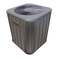
II − UNIT COMPONENTS
Unit components are illustrated in figure 1.
13ACX PARTS ARRANGEMENT
FIGURE 1
CAPACITOR
CONTACTOR
OUTDOOR FAN
COMPRESSOR
TIMED
OFF
CONTROL
(OPTION)
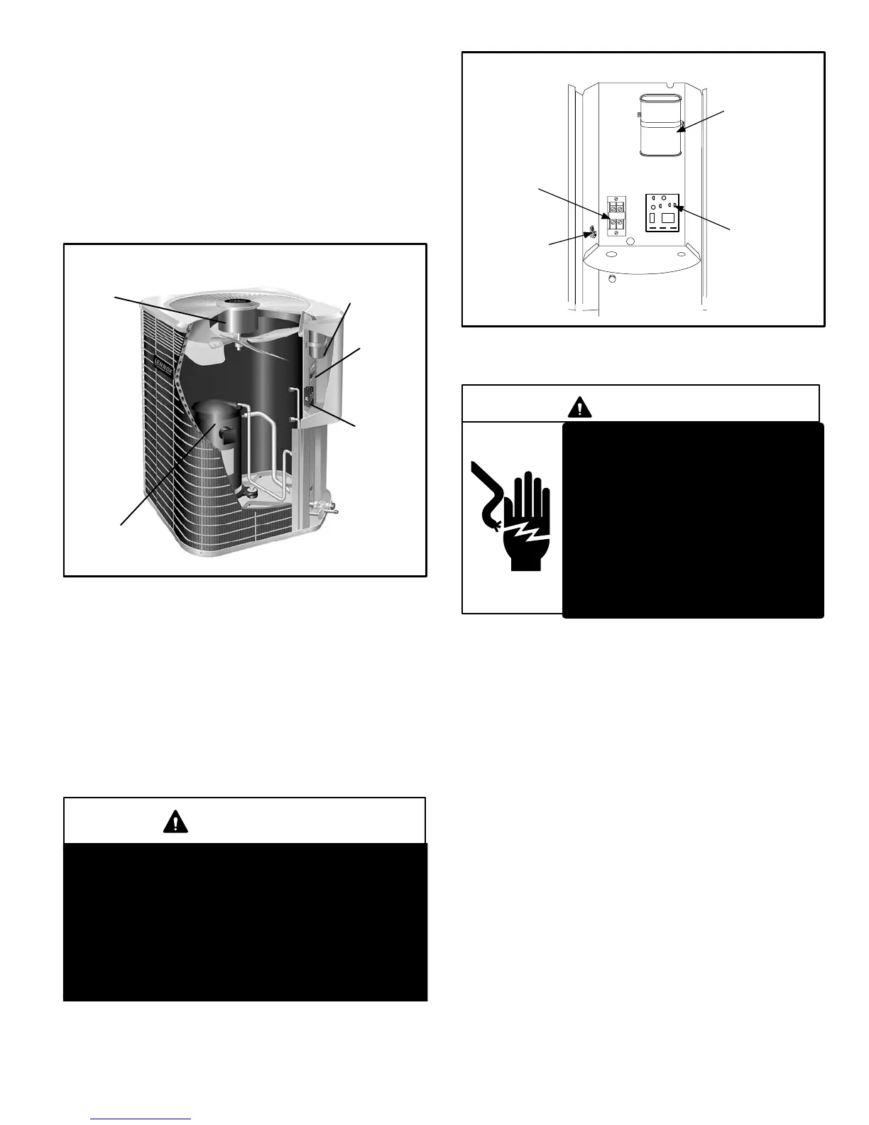
A − Control Box (Figure 2)
13ACX units are not equipped with a 24V transformer. All
24 VAC controls are powered by the indoor unit. Refer to
wiring diagram.
Electrical openings are provided under the control box cov-
er. Field thermostat wiring is made to color-coded pigtail
connections.
ELECTROSTATIC DISCHARGE (ESD)
Precautions and Procedures
CAUTION
Electrostatic discharge can affect electronic com-
ponents. Take precautions during unit installation
and service to protect the unit’s electronic controls.
Precautions will help to avoid control exposure to
electrostatic discharge by putting the unit, the con-
trol and the technician at the same electrostatic po-
tential. Neutralize electrostatic charge by touching
hand and all tools on an unpainted unit surface be-
fore performing any service procedure.
FIGURE 2
DUAL CAPACITOR
(C12)
COMPRESSOR
CONTACTOR
(K1)
CONTROL BOX
GROUNDING
LUG
TIMED OFF
CONTROL.
(OPTION)
1 − Compressor Contactor K1
DANGER
Shock Hazard
Remove all power at disconnect
before removing access panel.
Single phase 13ACX units use
single-pole contactors. Potential
exists for electrical shock resulting
in injury or death.
Line voltage exists at all compo-
nents (even when unit is not in op-
eration).
The compressor is energized by a single−pole contactor lo-
cated in the control box. See figure 2. K1 is energized by the
indoor thermostat terminal Y1 (24V) when thermostat de-
mand is present.
2 − Dual Capacitor C12
The compressor and fan in 13ACX series units use per-
manent split capacitor motors. The capacitor is located
inside the unit control box (see figure 2). A single dual"
capacitor (C12) is used for both the fan motor and the
compressor (see unit wiring diagram). The fan side and
the compressor side of the capacitor have different MFD
ratings. See side of capacitor for ratings.
3 − Timed Off Control TOC (option)
The time delay is electrically connected between thermostat
terminal Y and the compressor contactor. Between cycles,
the compressor contactor is delayed for 5 minutes ± 2 min-
utes but may last as long as 8 minutes. At the end of the
delay, the compressor is allowed to energize. When thermo-
stat demand is satisfied, the time delay opens the circuit to
the compressor contactor coil and the compressor is de−en-
ergized.
 Loading...