Page 8
5 − Evacuate the line set and indoor unit to an absolute
pressure of 23,000 microns (29.01 inches of mercury).
During the early stages of evacuation, it is desirable to
close the manifold gauge valve at least once to deter-
mine if there is a rapid rise in absolute pressure. A rap-
id rise in pressure indicates a relatively large leak. If this
occurs, repeat the leak testing procedure.
NOTE − The term absolute pressure means the total
actual pressure within a given volume or system, above
the absolute zero of pressure. Absolute pressure in a
vacuum is equal to atmospheric pressure minus vacu-
um pressure.
6 − When the absolute pressure reaches 23,000 microns
(29.01 inches of mercury), close the manifold gauge
valves, turn off the vacuum pump and disconnect the
manifold gauge center port hose from vacuum pump.
Attach the manifold center port hose to a nitrogen cylin-
der with pressure regulator set to 150 psig (1034 kPa)
and purge the air from the hose with nitrogen. Open the
manifold gauge valves to break the vacuum in the line
set and indoor unit. Close the manifold gauge valves.
CAUTION
Danger of Equipment Damage.
Avoid deep vacuum operation. Do not use compres-
sors to evacuate a system.
Extremely low vacuums can cause internal arcing and
compressor failure.
Damage caused by deep vacuum operation will void
warranty.
7 − Shut off the nitrogen cylinder and remove the manifold
gauge hose from the cylinder. Open the manifold gauge
valves to release the nitrogen from the line set and in-
door unit.
8 − Reconnect the manifold gauge to the vacuum pump,
turn the pump on, and continue to evacuate the line set
and indoor unit until the absolute pressure does not rise
above 500 microns (29.9 inches of mercury) within a
20−minute period after shutting off the vacuum pump
and closing the manifold gauge valves.
9 − When the absolute pressure requirement above has
been met, disconnect the manifold hose from the vacu-
um pump and connect it to an upright cylinder of R−410A
refrigerant. Open the manifold gauge valves to break the
vacuum from 1 to 2 psig positive pressure in the line set
and indoor unit. Close manifold gauge valves and shut
off the R−410A cylinder and remove the manifold gauge
set.
C − Charging
This system is charged with R−410A refrigerant which oper-
ates at much higher pressures than HCFC−22. The recom-
mended check expansion valve is approved for use with
R−410A. Do not replace it with a valve that is designed to be
used with HCFC−22. This unit is NOT approved for use with
coils that include metering orifices or capillary tubes.
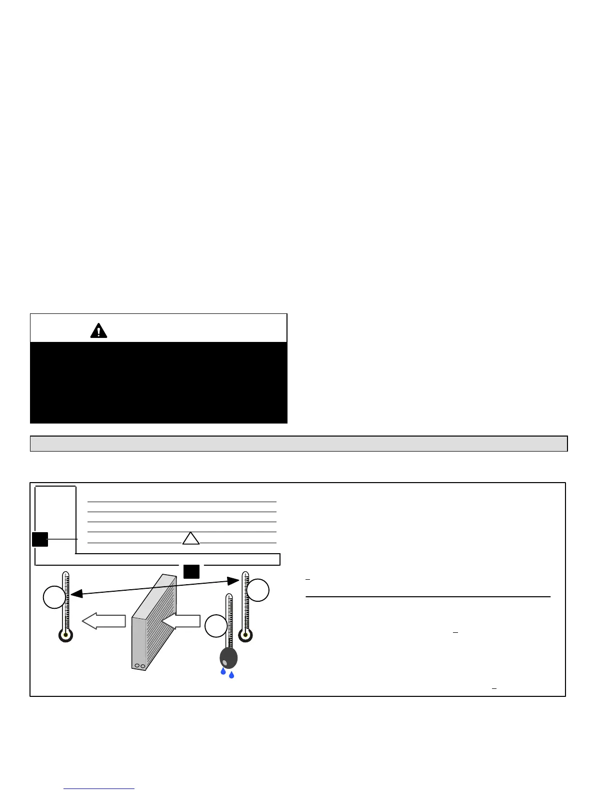
Check Indoor Airflow before Charging
NOTE − Be sure that filters and indoor and outdoor coils are clean before testing.
Check indoor airflow using the step procedures as illustrated in figure 11.
Step 1. Determine the desired DTMeasure entering air tempera-
ture using dry bulb (A) and wet bulb (B). DT is the intersecting value
of A and B in the table (see triangle).
Step 2. Find temperature drop across coilMeasure the coil’s dry
bulb entering and leaving air temperatures (A and C). Temperature
Drop Formula: (T
Drop
) = A minus C.
Step 3. Determine if fan needs adjustmentIf the difference be-
tween the measured T
Drop
and the desired DT (T
Drop
–DT) is within
+3º, no adjustment is needed. See examples: Assume DT = 15 and
A temp. = 72º, these C temperatures would necessitate stated ac-
tions:
Cº T
Drop
– DT = ºF ACTION
53º 19 – 15 = 4 Increase the airflow
58º 14 – 15 = −1 (within +3º range) no change
62º 10 – 15 = −5 Decrease the airflow
Step 4. Adjust the fan speedSee indoor unit instructions to in-
crease/decrease fan speed.
Changing air flow affects all temperatures; recheck temperatures to
confirm that the temperature drop and DT are within +3º.
DT
80 24 24 24 23 23 22 22 22 20 19 18 17 16 15
78 23 23 23 22 22 21 21 20 19 18 17 16 15 14
76 22 22 22 21 21 20 19 19 18 17 16 15 14 13
74 21 21 21 20 19 19 18 17 16 16 15 14 13 12
72 20 20 19 18 17 17 16 15 15 14 13 12 11 10
70 19 19 18 18 17 17 16 15 15 14 13 12 11 10
57 58 59 60 61 62 63 64 65 66 67 68 69 70
Temp.
of air
entering
indoor
coil ºF
INDOOR
COIL
DRY BULBDRY
BULB
WET
BULB
B
T
Drop
19º
A
Dry−bulb
Wet−bulb ºF
A
72º
B
64º
C
53º
air flowair flow
All temperatures are
expressed in ºF
FIGURE 11
 Loading...