Page 24
IMPORTANT
Use a thermocouple or thermistor electronic vacuum
gauge that is calibrated in microns. Use an instrument
capable of accurately measuring down to 50 microns.
WARNING
Danger of Equipment Damage. Avoid deep vacuum
operation. Do not use compressors to evacuate a
system. Extremely low vacuums can cause internal
arcing and compressor failure. Damage caused by
deep vacuum operation will void warranty.
Evacuating the system of non-condensables is critical for
proper operation of the unit. Non-condensables are defined
as any gas that will not condense under temperatures and
pressures present during operation of an air conditioning
system. Non-condensables and water suction combine with
refrigerant to produce substances that corrode copper
piping and compressor parts.
Electrical
In the U.S.A., wiring must conform with current local codes
and the current National Electric Code (NEC). In Canada,
wiring must conform with current local codes and the current
Canadian Electrical Code (CEC).
Refer to the furnace or air handler installation instructions
for additional wiring application diagrams and refer to unit
nameplate for minimum circuit ampacity and maximum
overcurrent protection size.
24VAC TRANSFORMER
Use the transformer provided with the furnace or air handler
for low‐voltage control power (24VAC - 40 VA minimum)
Refer to the unit nameplate for minimum circuit ampacity, and maximum
fuse or circuit breaker (HACR per NEC). Install power wiring and properly
sized disconnect switch.
NOTE — Units are approved for use only with copper conductors.
Ground unit at disconnect switch or to an earth ground.
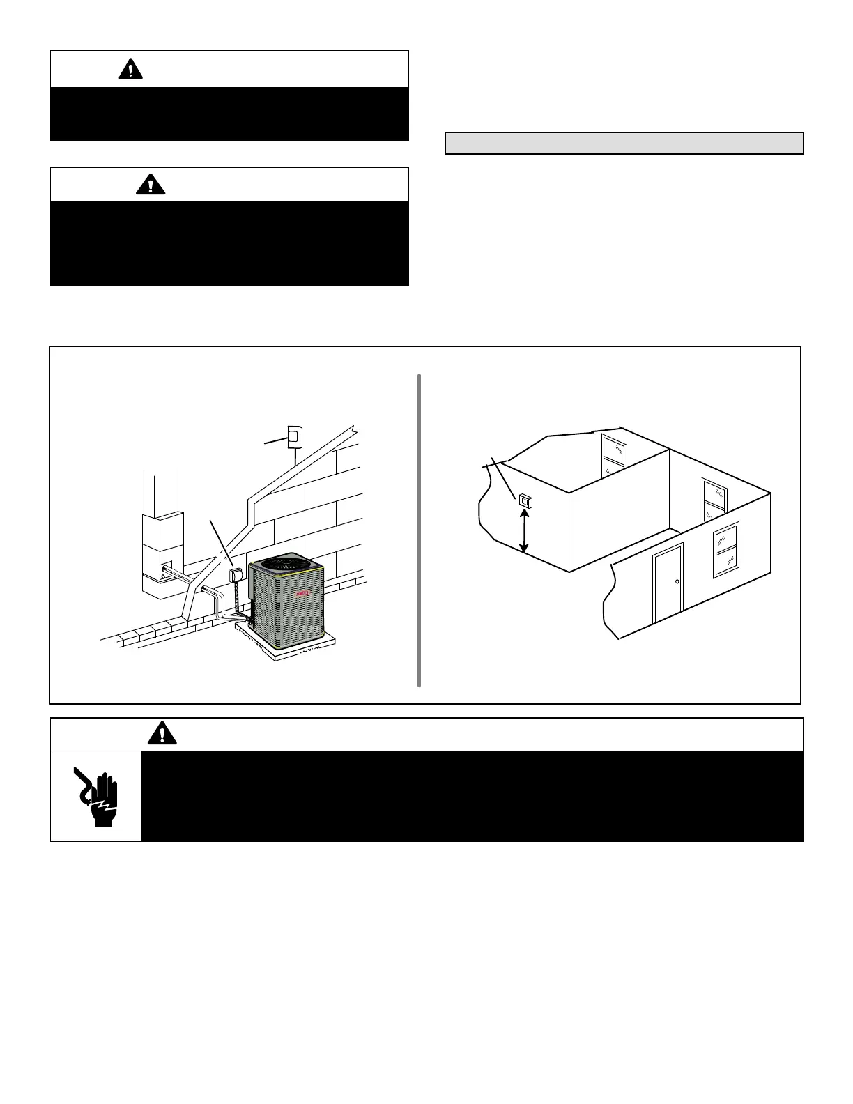
SIZE CIRCUIT AND INSTALL SERVICE
DISCONNECT SWITCH
NOTE — 24VAC, Class II circuit connections are made in the control
panel.
Install room thermostat (ordered separately) on an inside wall
approximately in the center of the conditioned area and 5 feet (1.5m) from
the floor. It should not be installed on an outside wall or where it can be
affected by sunlight or drafts.
THERMOSTAT
5 FEET
(1.5M)
INSTALL THERMOSTAT
SERVICE
DISCONNECT
SWITCH
MAIN FUSE BOX/
BREAKER PANEL
WARNING
Electric Shock Hazard. Can cause injury or death. Unit must be grounded in accordance with national and
local codes.
Line voltage is present at all components when unit is not in operation on units with single‐pole contactors.
Disconnect all remote electric power supplies before opening access panel. Unit may have multiple power
supplies.
 Loading...