# 48306B006 Page 13
roodtuO
.pmeT
F°
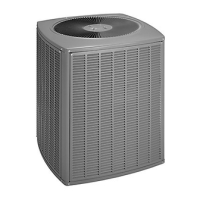
)F°1±(gniloocbuSdiuqiL
81- 42- 03- 63- 24- 84- 06-
5631514131315141
57 01 31 21 01 01 31 21
588111188 1111
59 7 9 01 7 7 9 01
501 6896689
511 3 5 6 3 3 5 6
Subcooling Values for
Fixed Orifice or TXV Systems
Table 6
3. Use a temperature/pressure chart for HCFC-22 to
determine the saturation temperature for the suction
line pressure reading.
4. Subtract the saturation temperature (according to the
chart) from the suction line temperature to determine
the superheat.
_____ ° Suction Line Temperature °F
_____ ° Saturation Temperature °F
_____ ° Superheat Value °F
–
=
Pressures higher than those listed indicate that the
system is overcharged. Pressures lower than those
listed indicate that the system is undercharged. Verify
adjusted charge using the approach method.
4. Use the same digital thermometer used to check
outdoor ambient temperature in Step 1 to check liquid
line temperature. Verify the unit charge using the
approach method.
5. Subtract the outdoor ambient temperature from the
liquid line temperature to determine the approach
temperature.
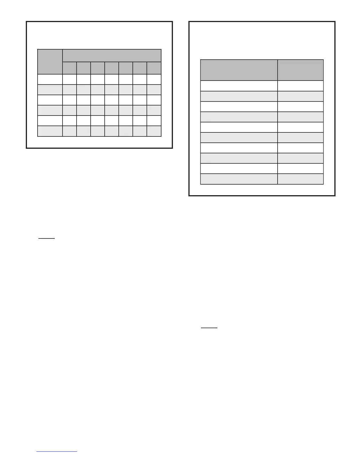
.pmeTtneibmAroodtuO
F°
taehrepuS
F°
0683
56 53
0703
57 62
0822
58 81
0921
59 8
0015
501 0
Superheat Values for
Fixed Orifice Systems
(80°DB/67°WB Return Air)
Table 7
5. Compare the superheat value with those shown in
Table 7. If superheat is greater than shown, add some
refrigerant. If superheat is less than shown, recover
some refrigerant.
Charge Using Approach Method (TXV Systems) –
Outdoor Temperatures 65°F or Above
The following procedure is intended as a general guide
and is for use on expansion valve systems only. For best
results, indoor temperature should 70°F to 80°F. Monitor
system pressures while charging.
1. Record outdoor ambient temperature using a digital
thermometer.
2. Attach high pressure gauge set and operate unit for
several minutes to allow system pressures to stabilize.
3. Compare stabilized pressures with those provided in
Table 8 on page 14. Minor variations in these pres-
sures may be expected due to differences in installa-
tions. Significant differences could mean that the
system is not properly charged or that a problem
exists with some component in the system.
_____ ° Liquid Line Temperature °F
_____ ° Outdoor Ambient Temperature °F
_____ ° Approach Temperature °F
–
=
6. Compare the approach value with those shown in
Table 9 on page 14. If the values to do not agree with
those provided in Table 9, add refrigerant to lower the
approach temperature or recover refrigerant from the
system to increase the approach temperature.
Check Charge Using Normal Operating Pressures
Use Table 8 on page 14 to perform maintenance checks.
Table 8 is not a procedure for charging the system. Minor
variations in these pressures may be due to differences in
installations. Significant deviations could mean that the
 Loading...