Page 7
3− Furnace Control (A3)
80UHG−2, −3 Models
80UHG−2 and −3 model units are equipped with the Len
nox SureLight ignition system. The system consis ts of
ignition control board (figure 6 with control ter minal desig
nations in table 4) and ignitor (figure 7). The boar d and ig
nitor work in combination to ensure furnace ignition and
ignitor dur ability. The SureLight integrated board controls
all major furnace operations. The board also features two
LED lights for troubles hooting and two accessory termi
nals rated at (4) four amps. See table 3 for troubles hoot
ing diagnostic codes. Table 1 and 2 show jack plug termi
nal designations. Units equipped with the Sur eLight
board can be used with either electronic or electro− me
chanical thermostats without modification. The Sur
eLight ignitor is made of dur able silicon− nitr ide. Ignitor
longevity is also enhanc ed by voltage ramping by the
control board. The board finds the lowest ignitor temper a
ture which will successfully light the burner, thus increas
ing the life of the ignitor. Each time power is applied to the
furnace, the SureLight board performs a selfcheck in
cluding ener giz ing the combus tion air blower for a period
of 1 second.
TABLE 1
SureLight BOARD J156 (J2) TERMINAL
DESIGNATIONS
PIN # FUNCTION
1 Combustion Air Inducer Line
2
Ignitor Line
3
Combustion Air Inducer Neutral
4
Ignitor Neutral
TABLE 2
SureLight BOARD J58 (J1) TERMINAL
DESIGNATIONS
PIN # FUNCTION
1 Primary Limit / Pressure Switch Out
2
Secondary Limit
3
24V
4
Not Used
5
Rollout Switch In
6
24V
7
Primary Limit In
8
Ground
9
Gas Valve In
10
Pressure Switch In
11
Rollout Switch Out
12
Gas Valve Out
a−Electronic Ignition (See Figure 5)
On a call for heat the SureLight control monitors the com
bustion air inducer pressure switch. The control will not be
gin the heating cycle if the prove switch is closed (by−
passed). Once the prove switch is determined to be open,
the combustion air inducer is energized. When the differ
ential in the prove switch is great enough, the prove switch
closes and a 15−second pre−purge begins. If the prove
switch is not proven within 2−1/2 minutes, the control goes
into Watchguard−Pressure Switch mode for a 5−minute re−
set period.
After the 15−second pre−purge period, the SureLight igni
tor warms up for 20 seconds during which the gas valve
opens at 19 seconds for a 4−second trial for ignition. The
ignitor stays energized for the first second of the 4−second
trial. 80UHG units equipped with control 10M9301: ignitor
remains energized during the 4 second trial until flame is
sensed. If ignition is not proved during the 4−second peri
od, the control will try four more times with an inter purge
and warm−up time between trials of 35 seconds. After a to
tal of five trials for ignition (including the initial trial), the
control goes into Watchguard−Flame Failure mode. After a
60−minute reset period, the control will begin the ignition
sequence again.
The SureLight control board has an added feature that
prolongs the life of the ignitor. After a successful ignition,
the SureLight control utilizes less power to energize the ig
nitor on successive calls for heat. The control continues to
ramp down the voltage to the ignitor until it finds the lowest
amount of power that will provide a successful ignition.
This amount of power is used for 255 cycles. On the 256th
call for heat, the control will again ramp down until the low
est power is determined and the cycle begins again.
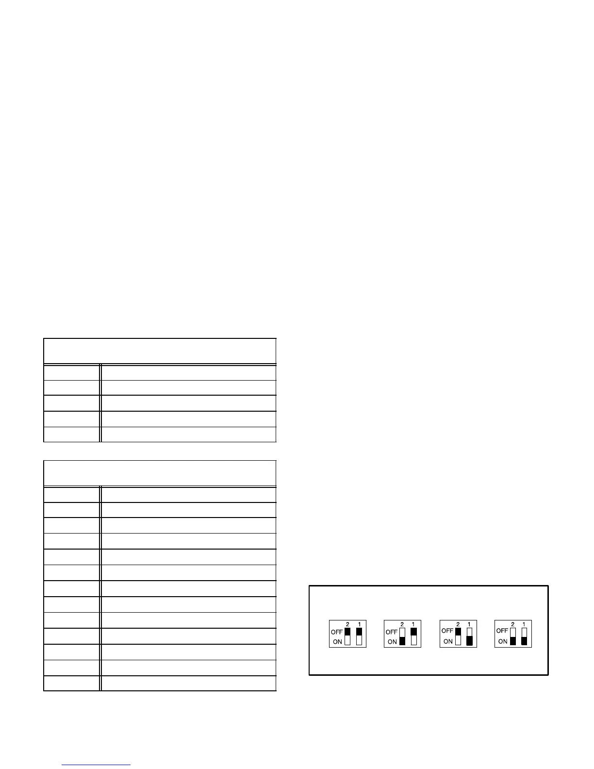
b−Fan Time Control
The fan on time of 45 seconds is not adjustable. Fan off
time (time that the blower operates after the heat demand
has been satisfied) can be adjusted by flipping the dip
switches located on the SureLight integrated control. The
unit is shipped with a factory fan off setting of 90 seconds.
Fan off time will affect comfort and is adjustable to satisfy
individual applications. See figure 4.
FIGURE 4
FANOFF TIME ADJUSTMENT
To adjust fan−off timing, flip dip switch to desired setting.
60sec. 90sec. 120sec. 180sec.
 Loading...


