507266-05 Page 37 of 58Issue 1933
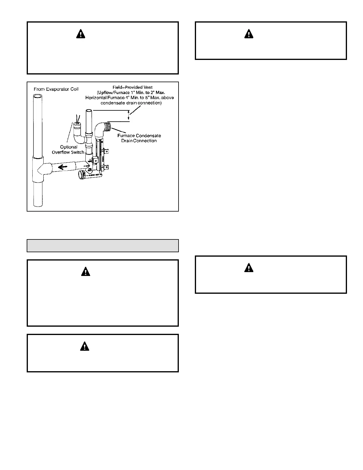
When combining the furnace and evaporator coil
drains together, the A/C condensate drain outlet must
be vented to relieve pressure in order for the furnace
pressure switch to operate properly.
IMPORTANT
Figure 59. Condensate Trap with Optional Overow
Switch
Gas Piping
If a exible gas connector is required or allowed by
the authority that has jurisdiction, black iron pipe shall
be installed at the gas valve and extend outside the
furnace cabinet. The exible connector can then be
added between the black iron pipe and the gas supply
line.
CAUTION
Do not exceed 600 in.-lbs. (50 ft.-lbs.) torque when
attaching the gas piping to the gas valve.
WARNING
1. Gas piping may be routed into the unit through either
the left or right hand side. Supply piping enters into the
gas valve from the side of the valve as shown in Figure
60 and Figure 61.
A low inlet pressure switch in LP/propane applications
is recommended.
IMPORTANT
2. When connecting gas supply, factors such as length
of run, number of ttings and furnace rating must be
considered to avoid excessive pressure drop. Table 8
lists recommended pipe sizes for typical applications.
NOTE: Use two wrenches when connecting gas piping
to avoid transferring to the manifold.
3. Gas piping must not run in or through air ducts,
clothes chutes, chimneys or gas vents, dumb waiters
or elevator shafts. Center gas line through piping hole.
Gas line should not touch side of unit. See Figure 60
and Figure 61.
4. Piping should be sloped 1/4 “ per 15 feet (6 mm per 5.6
m) upward toward the gas meter from the furnace. The
piping must be supported at proper intervals, every 8
to 10 feet (2.44 to 3.05 m), using suitable hangers or
straps. Install a drip leg in vertical pipe runs to serve as
a trap for sediment or condensate.
5. A 1/8” N.P.T. plugged tap or pressure post is located
on the gas valve to facilitate test gauge connection.
See Figure 62.
6. In some localities, codes may require installation of a
manual main shut-o valve and union (furnished by
installer) external to the unit. Union must be of the
ground joint type.
Compounds used on threaded joints of gas piping must
be resistant to the actions of liquied petroleum gases.
IMPORTANT
Leak Check
After gas piping is completed, carefully check all piping
connections (factory and eld installed) for gas leaks. Use
a leak detecting solution or other preferred means.
Never use an open ame to test for gas leaks. Check all
connections using a commercially available soap solution
made specically for leak detection.
The furnace must be isolated from the gas supply system
by closing its individual manual shut-o valve during any
pressure testing of the gas supply system at pressures
more than or equal to 1/2 psig (3.48 kPa, 14 inches w.c.).
 Loading...