Page 11
AC13 SERIES
1. Cut ends of the refrigerant lines square (free from
nicks or dents). Debur the ends. The pipe must remain
round, do not pinch end of the line.
2. Remove service cap and core from both the suction
and liquid line service ports.
3. Connect gauge low pressure side to liquid line service
valve.
4. To protect components during brazing, wrap a wet
cloth around the liquid line service valve body and
copper tube stub and use another wet cloth
underneath the valve body to protect the base paint.
5. Flow regulated nitrogen (at 1 to 2 psig) through the
refrigeration gauge set into the valve stem port
connection on the liquid line service valve and out of
the valve stem port connection on the suction service
valve. The TXV metering device at the indoor unit coil
will allow low pressure
nitrogen to flow through the
system.)
NOTE − The fixed orifice or TXV metering device at the
indoor unit will allow low pressure nitrogen to flow through
the system.)
NOTE − Use silver alloy brazing rods with five or six percent
minimum silver alloy for copper−to−copper brazing or 45
percent silver alloy for copper−to−brass or copper−to−steel
brazing.
6. Braze the liquid line to the liquid line service valve.
Turn off nitrogen flow.
IMPORTANT
Repeat procedure starting at paragraph 4 for brazing the
suction line to service port valve.
7. After all connections have been brazed, disconnect
manifold gauge set the from service ports and remove
wrapping. Reinstall the service port core for both of the
outdoor unit’s service valves.
Removing Indoor Unit Metering Device
Remove the existing HCFC−22 refrigerant flow control
orifice or thermal expansion valve from the indoor coil.
REPLACEMENT PARTS
If replacement parts are necessary for the indoor unit,
order kit 69J46 (LB−95325A). The kit includes the
following:
TEFLON RINGS (20)
BRASS NUTS (10)
LIQUID LINE ASSEMBLIES
(INCLUDES STRAINER) (10)
LIQUID LINE ORIFICE HOUSINGS (10)
LIQUID LINE
ASSEMBLY
COPPER
TUBE
PISTON
RETAINER
STRAINER
Figure 19. 69J46 Kit Components
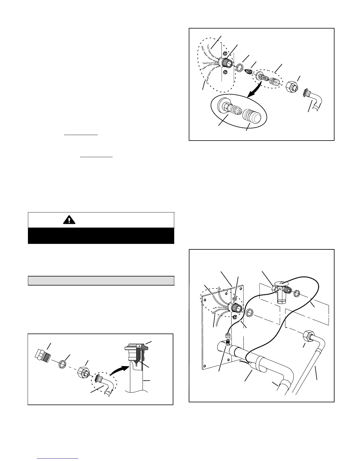
TYPICAL FIXED ORIFICE REMOVAL PROCEDURE
TEFLON RING
REMOVE AND DISCARD
VALVE STEM ASSEMBLY
(IF PRESENT)
FIXED
ORIFICE
(Uncased Coil Shown)
VALVE STEM
VALVE STEM CAP
BRASS NUT
LIQUID LINE ASSEMBLY
(INCLUDES STRAINER)
LIQUID LINE ORIFICE HOUSING
DISTRIBUTOR TUBES
DISTRIBUTOR
ASSEMBLY
Figure 20. Typical Fixed Orifice Removal
1. On fully cased coils, remove the coil access and
plumbing panels.
2. Remove any shipping clamps holding the liquid line
and distributor assembly.
3. Using two wrenches, disconnect liquid line from liquid
line orifice housing. Take care not to twist or damage
distributor tubes during this process.
4. Remove and discard fixed orifice, valve stem
assembly if present and Teflon ring as illustrated in
figure 20.
5. Use a field−provided fitting to temporary reconnect the
liquid line to the indoor unit’s liquid line orifice housing.
TYPICAL TXV REMOVAL PROCEDURE
TWO PIECE
PATCH PLATE
(UNCASED COIL
ONLY)
SUCTION
LINE
DISTRIBUTOR
ASSEMBLY
DISTRIBUTOR
TUBES
LIQUID
LINE
MALE EQUALIZER
LINE FITTING
SENSING
LINE
EQUALIZER
LINE
TXV
TEFLON
RING
(Uncased Coil Shown)
STUB END
TEFLON
RING
SENSING
BULB
LIQUID LINE
ORIFICE HOUSING
LIQUID LINE ASSEMBLY
WITH BRASS NUT
Figure 21. Typical TXV Removal
 Loading...