507621-01Issue 1720Page 10 of 23
Duct System and Filters
Duct System
The air handler is provided with anges for the connection
of the plenum and ducts. The air handler is equipped with
anges that can form a lter rack for the installation of the
air lter, or the lter may be installed as part of the return
air duct system.
Supply and return duct system must be adequately sized
to meet the system’s air requirements and static pressure
capabilities. The duct system should be insulated with
a minimum of 1” thick insulation with a vapor barrier in
conditioned areas or 2” minimum in unconditioned areas.
Supply plenum should be the same size as the anged
opening provided around the blower outlet and should
extend at least 3 ft. from the air handler before turning or
branching off plenum into duct runs. The plenum forms
an extension of the blower housing and minimizes air
expansion losses from the blower.
Filters
A lter is provided. Table 2 lists the lter size for each unit.
Installing Duct System
Install the conditioned air plenum, ducts and air lters
(not provided) in accordance with NFPA 90B Standard for
the Installation of Warm Air Heating and Air-Conditioning
Systems (latest edition).
Connect supply air duct to the ange on top of the air
handler. If an isolation connector is used, it must be
nonammable.
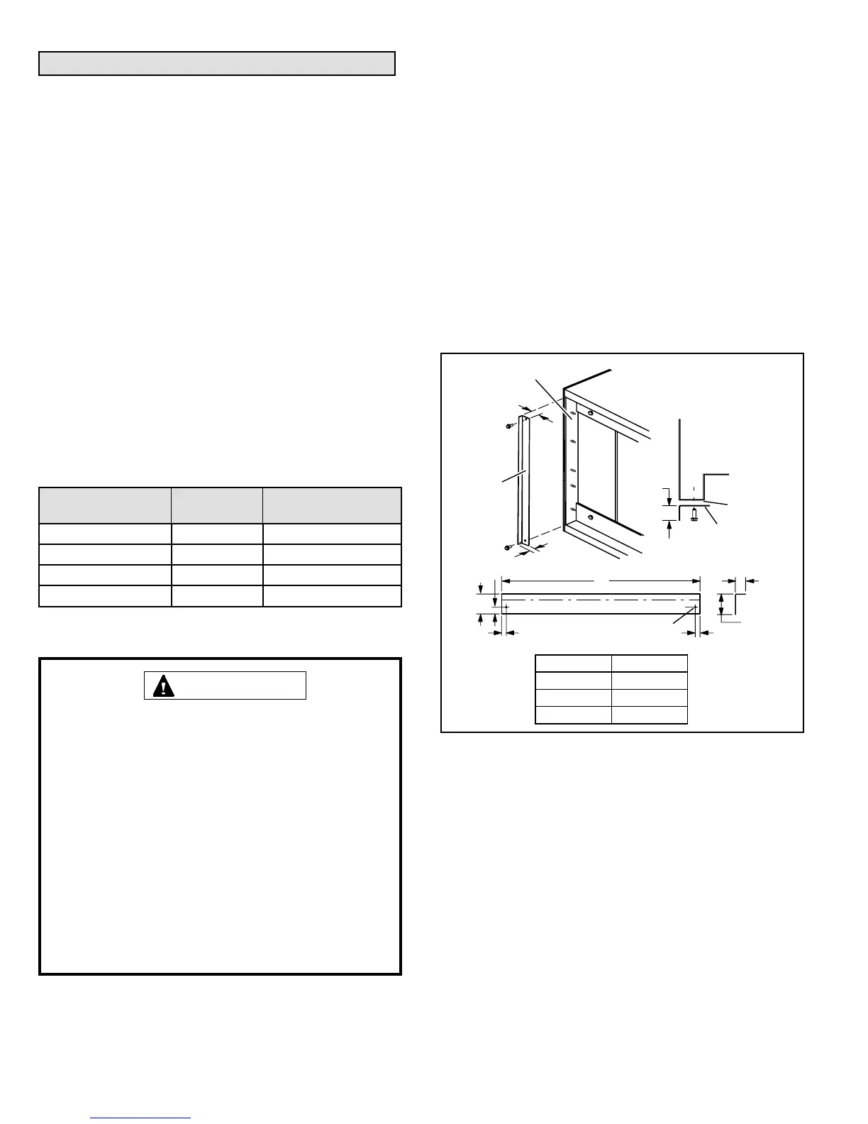
Field-Fabricated Return Air Duct Flange for
Horizontal Applications
A return air duct system is recommended, but not factory-
provided. If the unit is installed in a conned space or
closet, run a full-size return connection to a location outside
the closet.
Model Filter Size
Actual Minimum
Filter Size
-018 12” x 20” x 1 11.50” x 19.50” x .75”
-024 and -030 15” x 20” x 1 14.50” x 19.50” x .75”
-036 18” x 20” x 1 17.50” x 19.50” x .75”
-042, -048 and -060 18” x 24” x 1 17.50” x 23.50” x .75”
Table 2. Filters
If a high -efciency lter is being installed as part of
this system to ensure better indoor air quality, the lter
must be properly sized. High -efciency lters have a
higher static pressure drop than standard- efciency
glass/foam lters. If the pressure drop is too great,
system capacity and performance may be reduced.
The pressure drop may also cause the limit to trip
more frequently during the winter and the indoor coil
to freeze in the summer, resulting in an increase in the
number of service calls.
Before using any lter with this system, check the
specications provided by the lter manufacturer
against the data given in the appropriate Allied Air
Product Specications bulletin.
IMPORTANT
BOTTOM OF
CABINET
DUCT
ADAPTER
1−1/2
(38)
“A”
BRAKE DOWN 90 DEGREES
1/4 (6) DIA.
2−HOLES
“A”
−018 14−7/8 (378)
−024 & −030 18−3/8 (467)
−036 to −060
21−3/4 (552)
1−1/2(38)
3/4
(19)
3/4
(19)
1−1/2
(38)
3/4
(19)
1/2
(13)
3/4
(19)
DUCT
FLANGE
CABINET
DOOR FLANGE
UNIT SIZE
Figure 13. Cabinet and Duct Flange
 Loading...