507621-01 Issue 1720 Page 17 of 23
Air Flow — Cooling Blower Speed
The cooling blower speed is factory congured to provide
correct air ow for an outdoor unit that matches the cooling
capacity rating of the air handler.
If the outdoor unit is smaller than the maximum cooling
capacity rating for the air handler, the cooling blower speed
may need to be changed. Refer to blower performance
chart (table 3).
ELECTRIC SHOCK HAZARD!
Disconnect all power supplies before
servicing.
Replace all parts and panels before
operating.
Failure to do so can result in death or
electrical shock.
WARNING
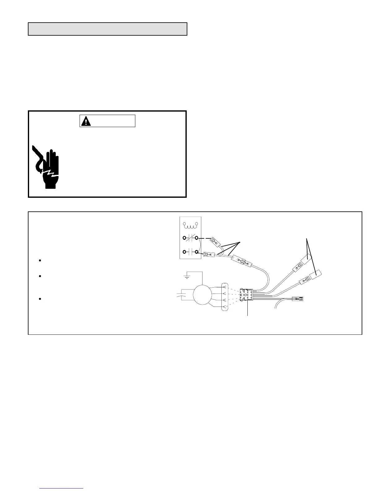
Figure 20
2
BLUE (MED)
RED (L0)
BLACK (HI)
YELLOW (COM)
5
BLOWER RELAY
BLOWER RELAY
PLASTIC CAPS
4-PIN
BLOWER CONNECTOR
HARNESS
NOTE - Refer to wiring diagram located on the
unit access panel, this figure, and blower
erformance (table 2).
All air data measured external to unit with 1
inch non-pleated air filter in place.
All factory settings are medium speed except
the -48 which is set to low speed from the
factory.
All data given while air handler is operating
with a dry DX coil.
3
6
4
2
4
3
1
GND
BRN / WHT
BRN
BLUE
RED
BLK
YEL+
MTR
Change Blower Speed
1. Disconnect all power supplies.
2. Remove the air handler access panel.
3. Locate pin number 2 on the blower relay. Two black
wires are connected to this terminal pin. One connects
to pin number 5 on the blower relay, one connects to
an in-line splice connecting to a blue wire.
4. Select the required blower motor speed connect red-
LO or black-HI and plug it into the 4-pin blower relay
harness connector.
NOTE: Reuse the factory-installed wire nut on the
unused wires.
5. Replace all panels.
6. Reconnect power.
 Loading...