507621-01Issue 1720Page 14 of 23
• The power supply must be sized and protected
according to the specications supplied on the product.
• This air handler is factory-congured for 240 volt,
single phase, 60 cycles. For 208-volt applications, see
“208 Volt Conversion” later in this section.
• Separate openings have been provided for 24V low
voltage and line voltage. Refer to the dimension
illustration for specic location.
• This unit is provided with holes for conduit. Use
provided caps to seal holes not used.
• Typical unit wiring (as well as wiring of optional eld-
installed electric heat) is given in gure 18. Refer to
the instructions provided with the electric heat section
for proper installation.
• For optional eld-installed electric heat applications,
refer to the instructions provided with the accessory
for proper installation.
USE COPPER CONDUCTORS ONLY!
WARNING
1. Disconnect all power supplies.
2. Remove the air handler access panel.
3. Route the eld supply wires to the air handler electrical
connection box.
4. Use UL-listed wire nuts to connect the eld supply
conductors to the unit black and yellow leads, and the
ground wire to ground terminal marked GND.
5. Replace the air handler access panel.
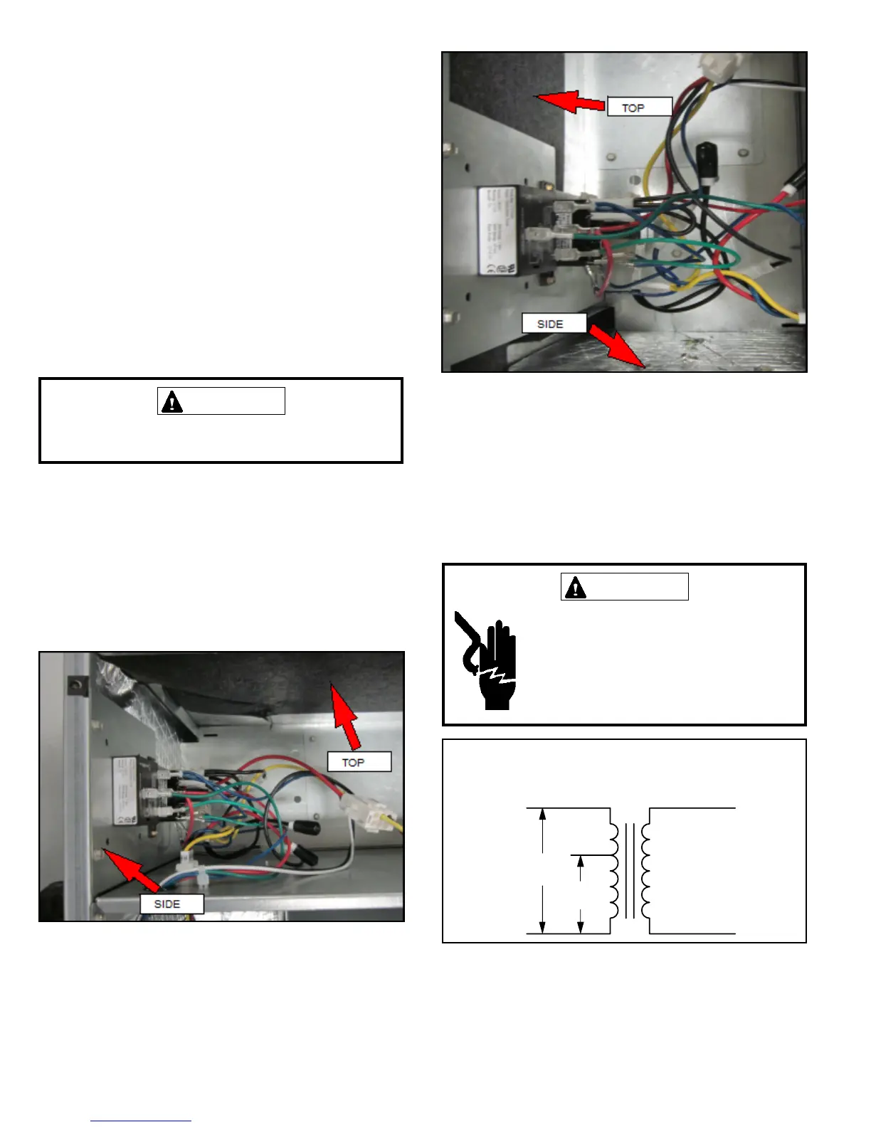
Figure 15
NOTE: To avoid the possibility of moisture damage to the
control in some right-hand discharge congurations, the
control panel can be relocated to the end panel as shown
in gure 16.
Figure 16
208 Volt Conversion
1. Disconnect all power supplies.
2. Remove the air handler access panel.
3. Using the wiring diagram located on the unit access
panel as a reference, move the 2 connected black
transformer leads from the 240 volt terminal on the
transformer to the 208 volt terminal on the transformer.
Electrically ground air handler. Connect
ground wire to ground terminal marked
“GND”.
Failure to do so can result in death or
electrical shock.
WARNING
208 / 240 VOLT TRANSFORMER
PRIMARY SECONDARY
240 Volts
208 Volts
Figure 17
 Loading...