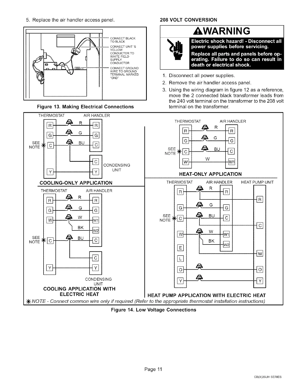
5. Replacetheairhandleraccesspanel,
208 VOLT CONVERSION
CONNECT BLACK
TO BLACK
CONNECT UNIT'S
YELLOW
CONDUCTORTO
WHITE FIELD
SUPPLY
CONDUCTOR
CONNECT GROUND
WIRE TO GROUND
TERMINAL MARKED
"GND"
Figure 13. Making Electrical Connections
_WARNING
1. Disconnect all power supplies.
2. Remove the air handler access panel.
3. Using the wiring diagram in figure 12 as a reference
move the 2 connected black transformer leads from
the 240 volt terminal on the transformer to the 208 volt
terminal on the transformer.
[]-
[]-
SEE
NOTE '- I_
[23-
THERMOSTAT AIR HANDLER
G
_---_ CONDENSING
UNIT
COOLING-ONLY APPLICATION
SEE
NOTE
THERMOSTAT AIR HANDLER
_]
CONDENSING
UNIT
COOLING APPLICATION WITH
ELECTRIC HEAT
THERMOSTAT AIR HANDLER
SEE ._ BU
NOTE_:'I]_ _]
% w %
HEAT-ONLY APPLICATION
SEE ,
NOTE _
THERMOSTAT
[]
[]
[]-
AIR HANDLER
_i _B° []
HEAT PUMP UNIT
[]
[]
[]
[]
HEAT PUMP APPLICATION WITH ELECTRIC HEAT
NOTE - Connect common wire only if required (Refer to the appropriate thermostat installation instructions)
Figure 14. Low Voltage Connections
Page 11
CB(X)26UH SERIES
 Loading...


