SELF TAPPING SCREWS -
_ _ OPTIONAL FOR
ATTACHING RETURN AIR
BRACKET _ # DUCT)
RAILS
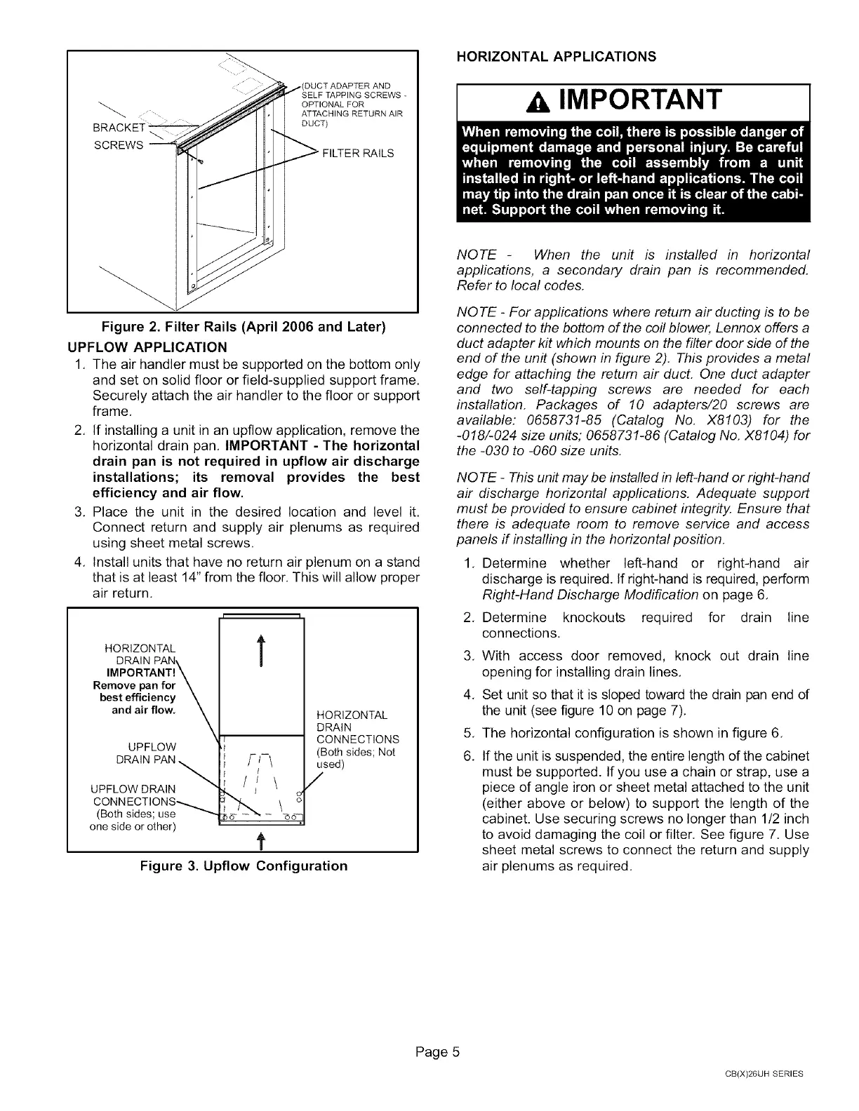
Figure 2. Filter Rails (April 2006 and Later)
UPFLOW APPLICATION
1. The air handler must be supported on the bottom only
and set on solid floor or field-supplied support frame.
Securely attach the air handler to the floor or support
frame,
2. If installing a unit in an upfiow application, remove the
horizontal drain pan, IMPORTANT - The horizontal
drain pan is not required in upflow air discharge
installations; its removal provides the best
efficiency and air flow.
3. Place the unit in the desired location and level it.
Connect return and supply air plenums as required
using sheet metal screws.
4. Install units that have no return air plenum on a stand
that is at least 14" from the floor. This will allow proper
air return.
HORIZONTAL
DRAIN PAN\
IMPORTANT!\
Remove pan for\
best efficiency\
and air flow. X
UPFLOW
DRAIN PAN _
UPFLOW DRAIN
CONNECTIONS_
(Both sides; use _
one side or other)
T
f
q
HORIZONTAL
DRAIN
CONNECTIONS
(Both sides; Not
used)
/
Figure 3. Upflow Configuration
HORIZONTAL APPLICATIONS
A IMPORTANT
NOTE - When the unit is installed in horizontal
applications, a secondary drain pan is recommended.
Refer to local codes.
NOTE - For applications where return air ducting is to be
connected to the bottom of the coil blower, Lennox offers a
duct adapter kit which mounts on the filter door side of the
end of the unit (shown in figure 2). This provides a metal
edge for attaching the return air duct. One duct adapter
and two self-tapping screws are needed for each
installation. Packages of 10 adapters/20 screws are
available: 0658731-85 (Catalog No. X8103) for the
-018/-024 size units; 0658731-86 (Catalog No. X8104) for
the -030 to -060 size units.
NOTE - This unit may be installed in left-hand or right-hand
air discharge horizontal appfications. Adequate support
must be provided to ensure cabinet integrity. Ensure that
there is adequate room to remove service and access
panels if installing in the horizontal position.
1. Determine whether left-hand or right-hand air
discharge is required. If right-hand is required, perform
Right-Hand Discharge Modification on page 6,
2. Determine knockouts required for drain line
connections,
,
4.
5.
6.
With access door removed, knock out drain line
opening for installing drain lines.
Set unit so that it is sloped toward the drain pan end of
the unit (see figure 10 on page 7).
The horizontal configuration is shown in figure 6.
If the unit is suspended, the entire length of the cabinet
must be supported. If you use a chain or strap, use a
piece of angle iron or sheet metal attached to the unit
(either above or below) to support the length of the
cabinet. Use securing screws no longer than 1/2 inch
to avoid damaging the coil or filter. See figure 7. Use
sheet metal screws to connect the return and supply
air plenums as required.
Page 5
CB(X)26UH SERIES
 Loading...


