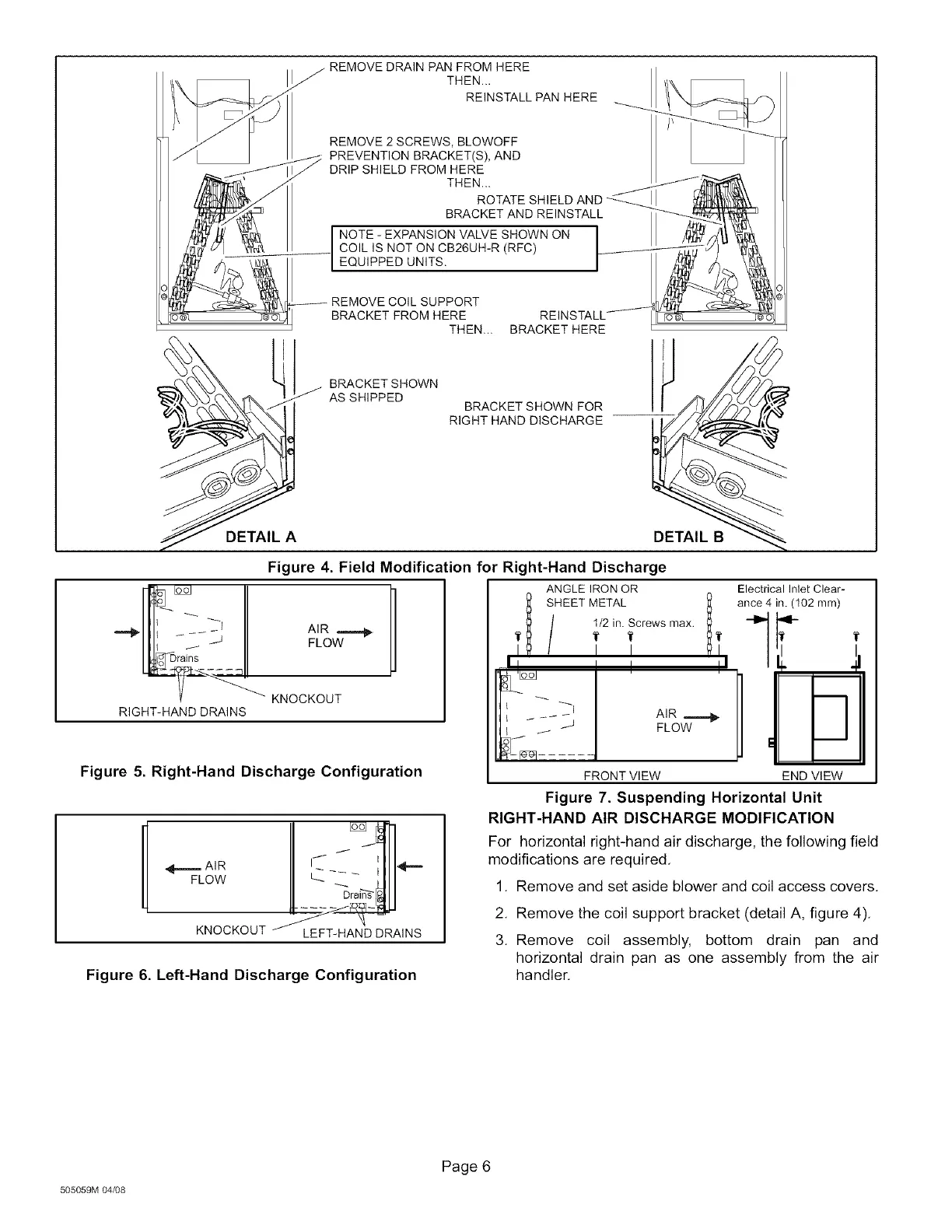
j REMOVE DRAIN PAN FROM HERE
THEN...
REINSTALL PAN HERE
REMOVE 2 SCREWS, BLOWOFF
__ PREVENTION BRACKET(S), AND
J
DRIP SHIELD FROM HERE
THEN...
ROTATE SHIELD AND
BRACKET AND REINSTALL
NOTE - EXPANSION VALVE SHOWN ON
COIL IS NOT ON CB26UH-R (RFC)
EQUIPPED UNITS.
REMOVE COIL SUPPORT
BRACKET FROM HERE
THEN... BRACKET HERE
BRACKET SHOWN
AS SHIPPED
BRACKET SHOWN FOR
RIGHT HAND DISCHARGE
RIGHT-HAND DRAINS
Figure 4. Field Modification for Right-Hand Discharge
ANGLE IRON OR
_1 iHEET METAL
t/2 in. Screws max.
AIR _ I_ I_
FLOW I I
K.OCKO
FRONT VIEW
Figure 5. Right-Hand Discharge Configuration
ElectricalInlet Clear-
1_ ance 4 in. (102 mm)
II , 41
UI
END VIEW
II @
/ f J
_ AIR I.... _=.
F.ow!.j
K OCKOO
Figure 6. Left-Hand Discharge Configuration
Figure 7. Suspending Horizontal Unit
RIGHT-HAND AIR DISCHARGE MODIFICATION
For horizontal right-hand air discharge, the following field
modifications are required.
1. Remove and set aside blower and coil access covers.
2. Remove the coil support bracket (detail A, figure 4).
3. Remove coil assembly, bottom drain pan and
horizontal drain pan as one assembly from the air
handler.
505059M 04/08
Page 6
 Loading...


