4, Removetwo screws,blowoffpreventionbracket
(whereused;seetable2),andhorizontaldripshield.
Rotatethebrackets180°andreinstallusingthesame
screws,
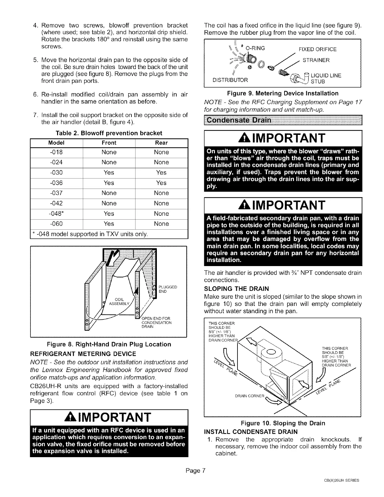
5, Movethehorizontaldrainpantotheoppositesideof
thecoil.Besuredrainholestowardthebackoftheunit
areplugged(seefigure8).Removetheplugsfromthe
frontdrainpanports.
6, Re-installmodifiedcoil/drainpan assemblyin air
handlerinthesameorientationasbefore.
7, Installthecoilsupportbracketontheoppositesideof
theairhandler(detailB,figure4),
Table2.Blowoffpreventionbracket
Model Front Rear
-018 None None
-024 None None
-030 Yes Yes
-036 Yes Yes
-037 None None
-042 None None
-048" Yes None
-060 Yes None
* -048 model supported in TXV units only.
The coil has a fixed orifice in the liquid line (see figure 9),
Remove the rubber plug from the vapor line of the coil.
I10
\\ O-RING FIXED ORIFICE
STRAINER
// LIQUID LINE
DISTRIBUTOR STUB
Figure 9. Metering Device Installation
NOTE - See the RFC Charging Supplement on Page 17
for charging information and unit match-up.
IMPORTANT
i
PLUGGED
END
PEN END FOR
CONDENSATION
DRAIN
Figure 8. Right-Hand Drain Plug Location
REFRIGERANT METERING DEVICE
NOTE - See the outdoor unit installation instructions and
the Lennox Engineering Handbook for approved fixed
orifice match-ups and appfication information.
CB26UH-R units are equipped with a factory-installed
refrigerant flow control (RFC) device (see table 1 on
Page 3).
A IMPORTANT
AkIMPORTANT
The air handler is provided with ¾" NPT condensate drain
connections.
SLOPING THE DRAIN
Make sure the unit is sloped (similar to the slope shown in
figure 10) so that the drain pan will empty completely
without water standing in the pan.
THIS CORNER
SHOULD BE
5/8" (+/- 1/8")
HIGHER THAN
THIS CORNER
SHOULD BE
5/8" (+/- 1/8")
HIGHER THAN
DRAIN CORNER
DRAIN CORNER
Figure 10. Sloping the Drain
INSTALL CONDENSATE DRAIN
1. Remove the appropriate drain knockouts. If
necessary, remove the indoor coil assembly from the
cabinet,
Page 7
CB(X)26UH SERIES