Page 27
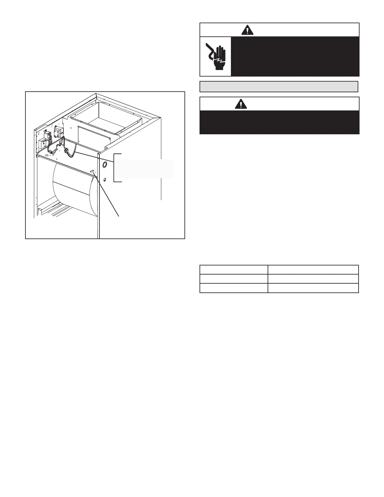
1 - Disconnect all power supplies.
2 - Remove the air handler access panel.
3 - Route the eld supply wires to the air handler
electrical connection box.
4 - Use UL-listed wire nuts to connect the eld supply
conductors to the unit black and yellow leads, and
the ground wire to ground terminal marked GND.
5 - 5. Replace the air handler access panel.
CONNECT BLACK AND
YELLOW WIRES TO
FIELD-PROVIDED
CONDUCTORS.
CONNECT GROUND
WIRE TO GROUND
TERMINAL MARKED
“GND”
FIGURE 23. Making Electrical Connections
208 VOLT CONVERSION
1 - Disconnect all power supplies.
2 - Remove the air handler access panel.
3 - Using the wiring diagram located on the unit access
panel as a reference, move the 2 connected black
transformer leads from the 240 volt terminal on
the transformer to the 208 volt terminal on the
transformer.
WARNING
Electrically ground air handler. Connect
ground wire to ground terminal marked
“GND”.
Failure to do so can result in death or
electrical shock.
Inspecting and Replacing Filters
IMPORTANT
Filter access door must be in place during unit operation.
Excessive warm air entering the unit from unconditioned
space may result in water blow-o problems.
Filters may be duct-mounted or installed in the cabinet. A
lter is installed at the factory. Note that lter access door
ts over access panel. Air will leak if the access panel is
placed over the lter door.
Filters should be inspected monthly and must be cleaned
or replaced when dirty to assure proper furnace operation.
To replace lter:
1 - Loosen the thumbscrews holding the lter panel in
place.
2 - Slide the lter out of the guides on either side of
cabinet.
3 - Insert new lter.
4 - Replace panel.
See table 3 for replacement lter sizes.
TABLE 6. Filter Dimensions
CBA25UHV Filter Size – In. (mm)
-018/024, -030, -036 15 x 20 x 1 (381 x 508 x 25)
-042, -048, -060 18 x 20 x 1 (457 x 508 x 25)
 Loading...