Page 4
Model Number Identication
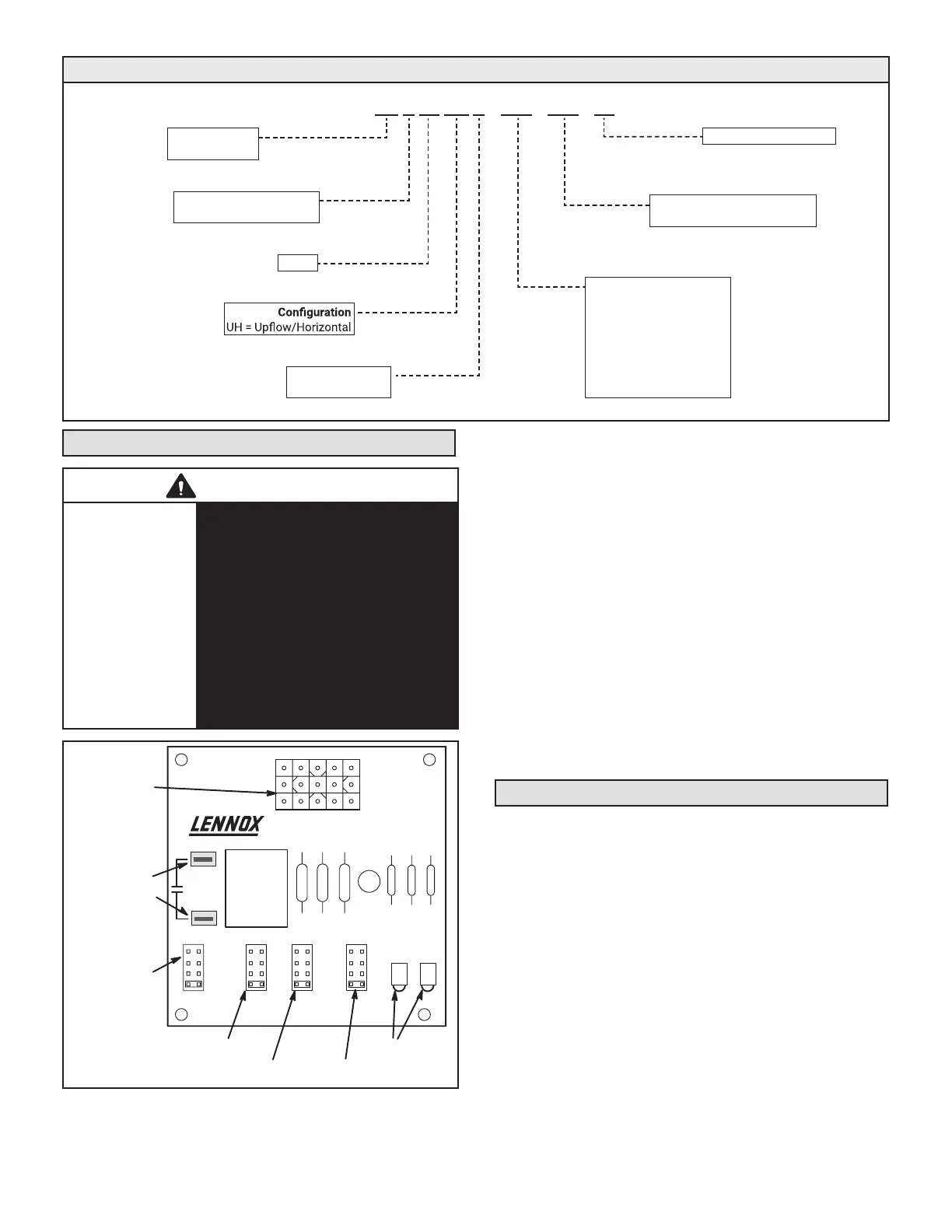
CB A 25 UH V - 030 - 230 - 10
Unit Type
CB = Air Handler
Refrigerant Type
A = Aluminum Coil/R-410A
Series
Nominal Cooling Capacity
018 = 1.5 tons
024 = 2 tons
030 = 2.5 tons
036 = 3 tons
042 = 3.5 tons
048 = 4 tons
060 = 5 tons
Minor Revision Number
Voltage
230 = 208/230V-1 phase-60hz
Blower Motor
V = Variable Speed
Adjusting the BDC3 Blower Control
WARNING
ELECTROSTATIC
DISCHARGE
(ESD)
Precautions and
Procedures
Electrostatic discharge can aect
electronic components. Take care
during unit installation and service to
protect the unit’s electronic controls.
Precautions will help to avoid control
exposure to electrostatic discharge
by putting the unit, the control and the
technician at the same electrostatic
potential. Touch hand and all tools
on an unpainted unit surface before
performing any service procedure to
neutralize electrostatic charge.
JP1 15 PIN
PLUG (BOARD
TO MOTOR)
4
3
2
1
TES
T
-
+
NOR
M
ADJUSTHEAT COOL DELAY CFM RUN
24V/1A
SERVICE
JP1
24V ACCESSORY
CONTACTS –
RATED FOR 1 AMP
OR LESS
OPERATIONAL
SELECTOR PINS
(AFFECTS BOTH
HEATING AND
COOLING MODES)
DIAGNOSTIC
LEDS
HEATING SPEED
SELECTOR PINS
COOLING SPEED
SELECTOR PINS
FAN DELAY
SELECTOR PINS
4
3
2
1
4
3
2
1
QC1
QC2
FIGURE 1. BDC3 Variable Speed Control Selections
Merit
®
CBA25UHV units are equipped with a vari-
able-speed motor that is capable of maintaining a spec-
ied CFM throughout the external static range. A particu-
lar CFM can be obtained by positioning jumpers (COOL,
HEAT, and ADJUST) on the BDC3 control.
The jumpers are labeled 1, 2, 3, and 4. This indicates
the selected air volume (CFM). The ADJUST jumper is
labeled Test, -, +, and Norm. The - and + pin settings are
used to add or subtract a percentage of the CFM select-
ed. The Test jumper is used to operate the motor in the
test mode. The delay jumper controls the timing pattern in
which the fan delay occurs.
Figure 1 illustrates the BDC3 control. Use tables on pages
5 and 6 to determine the correct air volume for heat and
cool speed taps.
Diagnostic LEDs located on the BDC3 control to assist in
servicing the unit. Read the jumper settings section before
adjusting blower speed. Refer to page 5 for identication
and information.
Adjusting the Blower Speed
Diagnostic LEDs
1 - RUN LED indicates there is a demand for the blower
motor to run.
2 - CFM LED indicates the cubic feet per minute at
which the unit is operating. The light ashes once
for approximately every 100 CFM. For example, if
the unit is operating at 1000 CFM, CFM LED will
ash 10 times. If the CFM is 1150, CFM LED will
ash 11 full times plus one fast or half ash.
At times, the light may appear to icker or glow. This is
normal and occurs when the control is communicating
with the motor between cycles.
Move the jumper pins to select the blower speed needed
to meet application CFM requirements.
 Loading...