Page 7
8 - Refer to instructions provided with outdoor unit for
leak testing, evacuating and charging procedures.
9 - Install access panel.
TABLE 2. Refrigerant Line Sizes
Model
Liquid
Line
Vapor
Line
Line Sets
-018
-024
-030
-036
3/8ʺ
(10mm)
3/4ʺ
(19mm)
L15 line set sizes are
dependant on unit
match-up. See Product
Specications (EHB) for
outdoor unit to determine
correct line set sizes
-042
-048
3/8ʺ
(10mm)
7/8"
(22mm)
-060
3/8ʺ
(10mm)
7/8"
(22mm)
Field fabricated
Installing the Condensate Drain
MAIN DRAIN
Connect the main drain and route downward to drain line
or sump. Do not connect drain to a closed waste system.
See Figure 8 for typical drain trap conguration.
OVERFLOW DRAIN
It is recommended that the overow drain is connected to
an overow drain line for all units. If overow drain is not
connected, it must be plugged with provided cap.
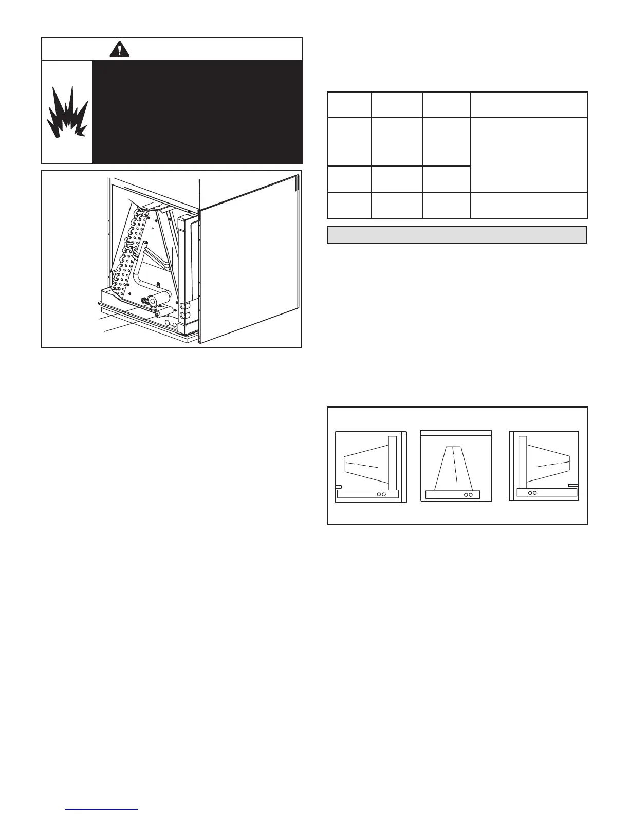
For downow orientation, the overow drain MUST be
connected and routed to a overow drain line. See Fig-
ure 7 for main and overow drain locations based on coil
orientation.
LEFT-HAND AIR
DISCHARGE
MAIN DRAIN ON
RIGHT
OVERFLOW
DRAIN ON LEFT
UP-FLOW OR
DOWN-FLOW
RIGHT-HAND AIR
DISCHARGE
FIGURE 7. Main and Overow Drain Locations
Based on Coil Orientation
BEST PRACTICES
The following best practices are recommended for the
condensate removal process:
• Main and overow drain lines should NOT be smaller
than both drain connections at drain pan.
• Overow drain line should run to an area where home-
owner will notice drainage.
• It is recommended that the overow drain line be vented
and a trap installed. Refer to local codes.
• Condensate drain lines must be congured or provided
with a cleanout to permit the clearing of blockages and
for maintenance without requiring the drain line to be
cut.
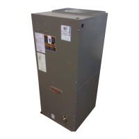
WARNING
Danger of explosion!
Can cause equipment damage, injury, or
death.
When using a high pressure gas such as dry
nitrogen to pressurize a refrigeration or air
conditioning system, use a regulator that can
control the pressure down to 1 or 2 psig (6.9
to 13.8 kPa).
AIR HANDLER UNIT
LIQUID LINE
FIGURE 6. Brazing Connections
NOTE – CBA27UHE series air handlers use nitrogen or
dry air as a holding charge. If there is no pressure when
the rubber plugs are removed, check the coil for leaks
before installing. After installation, pull a vacuum on the
line set and coil before releasing the unit charge into the
system.
NOTE – See outdoor unit instructions on how to ow nitro-
gen through line sets.
1 - Remove access panel.
2 - Remove the refrigerant line caps from the refrigerant
lines.
3 - Use a wet rag to protect TXV sensing bulb (or
remove it) when brazing suction line connections.
4 - Place a wet rag against piping plate and around
the suction line connection. The wet rag must be in
place to guard against damage to the paint.
5 - With the wet rag in place, position a eld provided
elbow tting to the air handler’s suction line and line
set. Start nitrogen ow before brazing.
6 - After the procedure is completed then remove the
wet rag.
7 - Place wet rag against piping plate and around the
liquid line connection. Position liquid line elbow to air
handler’s suction line and to line set. Start nitrogen
ow and begin brazing both connections and after
procedure is completed then remove both wet rags.
 Loading...