Page 21
TO PLACE CONTROL IN TEST MODE:
1- Turn off all power to avoid damaging the circuit board.
2- Make sure all control terminals are connected as shown on unit
wiring diagram before attempting to place control in test mode.
See NOTE below.
NOTE - Control will not go into test mode when disconĆ
nected from unit. Unit load must be applied to control termiĆ
nals before the control will go into test mode.
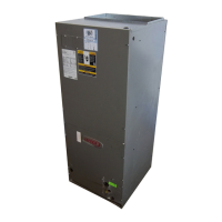
3- Connect jumper to TST" pins as shown.
4- Turn indoor thermostat to heat mode and adjust to highest temperaĆ
ture setting.
5- Turn on power to unit.
6- See Table 1 for control timings in TST" mode.
7- Be sure to turn off power and remove jumper when test is complete.
Turn on power and re-adjust thermostat.
IMPORTANT
Prevent control damage. Avoid contact with other
control terminals or control components.
FIGURE 7
d- COM" Terminal
Terminal COM" provides 24VAC common.
e- HLD" Terminal
Terminal HLD" holds an internal timer in place between
thermostat demands and allows the unit to continue timĆ
ing upon resumption of thermostat demand. When therĆ
mostat demand is present, the control is allowed to count
down to the next defrost. Terminal HLD" is connected
directly to thermostat demand.
f- OUT" Terminal
Terminal OUT" controls defrost when connected to one
side of the defrost relay coil. An internal relay conĆ
nected to terminal OUT" closes (allowing an internal
path from OUT" to COM") to allow external defrost
relay to energize and initiate defrost. At the end of the
defrost period, the internal relay connected to terminal
OUT" opens to de-energize the external defrost relay.
g- RST" Terminal
Terminal RST" resets the internal timer when power is reĆ
moved and begins timer operation when power is returned.
Terminal RST" is connected to terminal COM" through a
set of normally closed defrost relay contacts. When the deĆ
frost relay contacts open terminal RST" loses power (the
path through RST" is disrupted) and internal timer is reset.
The control resumes timing when the defrost relay contacts
close.
h- TST" Pins
Each board is equipped with a set of test pins for use in
troubleshooting the unit. When jumpered together, these
pins reduce the control timing to a fraction of the original
time (see table 1 and figure 7).
IMPORTANT
Prevent control damage.
Control will begin test mode only if normal load
is applied to control terminals. Do not attempt
to operate or test control out of unit.
A defrost period can last up to 14 minutes and can be termiĆ
nated two ways. First, if the defrost pressure switch does not
open within 14 minutes after defrost begins, the internal timer
(by opening the internal path from OUT" to COM") will de-enĆ
ergize the defrost relay and the unit will resume normal operaĆ
tion. Second, if the defrost pressure switch opens during the
14 minute defrost period, the defrost relay is de-energized
and the unit resumes normal operation. Refer to figure 8.
 Loading...