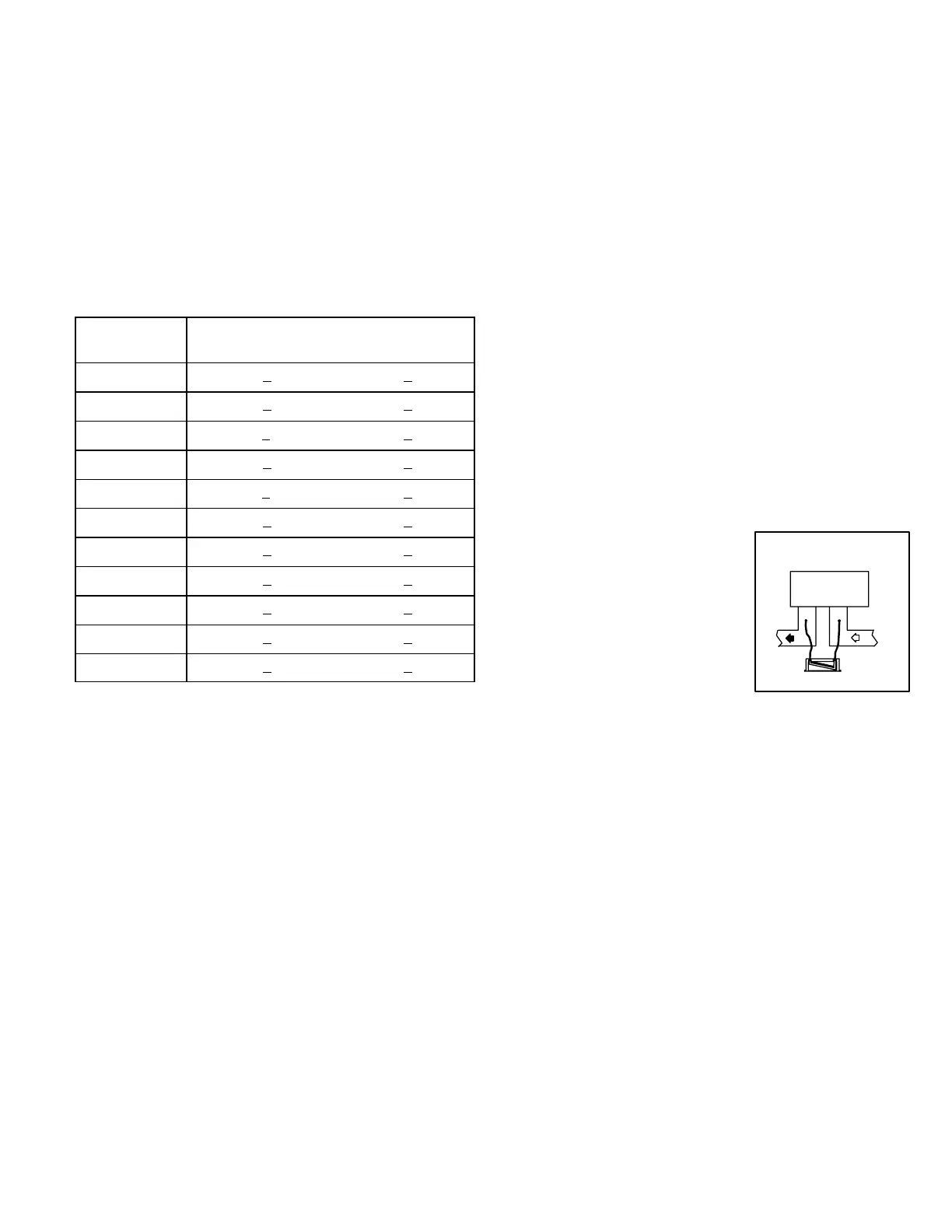
STATIC PRESSURE
TAP LOCATIONS
MANOMETER
UNIT
FIGURE 19
Page 44
APPROACH TEMPERATURE =
LIQUID TEMPERATURE - AMBIENT TEMPERATURE.
If ambient temperature is above 60° F (15° C), read liquid line
temperature. Approach temperature is the difference between
liquid line temperature and ambient temperature.
CAUTION-Use the same thermometer for both temperature
readings.
Approach temperature is shown in table 16. Refrigerant
must be added to lower approach temperature. Remove reĆ
frigerant from system to increase approach temperature.
TABLE 16
APPROACH TEMPERATURE
UNIT
LIQUID TEMP. MINUS
AMBIENT TEMP.
CHP16-024 7°F + 1 (3.9°C + 0.5)
CHP16-030 9°F + 1 (5.0°C + 0.5)
CHP16-036 11°F + 1 (6.0°C + 0.5)
CHP16-048 9°F + 1 (5.0°C + 0.5)
CHP16-060 11°F + 1 (6.0°C + 0.5)
CHP20-024 7°F + 1 (3.9°C + 0.5)
CHP20-030 7°F + 1 (3.9°C + 0.5)
CHP20-036 10°F + 1 (5.6°C + 0.5)
CHP20-042 6°F + 1 (3.3°C + 0.5)
CHP20-048 7°F + 1 (3.9°C + 0.5)
CHP20-060 12°F + 1 (6.7°C + 0.5)
If ambient temperature is less than 60° F (16° C), air flow
must be restricted to achieve pressures in the 200-250 psig
range. These higher pressures are necessary for checking
charge. To accomplish this, block the outdoor coil from top to
bottom evenly from both ends.
VIII-HEATING SYSTEM SERVICE CHECKS
A-Heating - Heat Pump
1- Set thermostat switch in Heat" position and blower
switch in On" or Auto" position. Set heating adjustment
lever above room temperature. Close unit disconnect
switch.
2- Compressor will cycle on demand from room thermoĆ
stat and outdoor coil fan will cycle with compressor.
Blower will operate according to position of blower
switch on thermostat.
3- A defrost control is used to prevent excessive outdoor
coil icing. As a defrost cycle is initiated, the reversing
valve switches, inducing heat to outdoor coil. Outdoor
fan stops during this process.
B-Heating - Optional Electric Heat
1- When heat requirements exceed heat pump capacity,
the thermostat automatically activates the optional
electric heat through W2.
IX-INDOORā BLOWER
OPERATION / ADJUSTMENT
Unit is equipped with direct drive, multi-speed indoor
blower. See unit wiring diagram for factory setting. Table
17 gives minimum blower speeds for CHP16 & 20 units
equipped with optional electric heat.
A-Blower Operation
1- Blower operation is manually set at the thermostat
subbase fan switch. When fan switch is in On" posiĆ
tion, blower operates continuously.
2- When fan switch is in Auto" position, blower will
cycle with demand. Blowers and entire unit will be off
when system switch is in Off" position.
To Measure Discharge Static Pressure:
a-Measure tap locations (figure 19).
b-Punch a 1/4" diameter hole. Insert manometer hose
flush with the inside edge of
hole or insulation. Seal
around hole with PermaĆ
gum. Connect the zero end
of the manometer to the disĆ
charge (supply) side of the
system. Connect other end
of manometer to the return
duct as above.
c-With only the blower motor running, observe the maĆ
nometer reading.
d-Seal around the hole when check is complete.
3- The CFM can be adjusted by changing the motor speed
taps. Follow the blower speed change instructions beĆ
low.
B-Blower Operation Adjustment
208-230 Volt Units - Blower speed selection is accomĆ
plished by changing the taps at the harness connector at
the blower motor. See figure 20 and unit diagram.
460-575 Volt Units-Blower speed selection is accomĆ
plished by changing the J38 blower speed jack in the return
air section. See unit wiring diagram.
IMPORTANTĊTo prevent motor burnout, never connect
more than one motor lead to any one connection. Black
and blue motor taps must be connected together when
operating on low or medium speeds. Tape unused motor
leads separately.
 Loading...