10
NOTE: DIAGRAMS & ILLUSTRATIONS ARE NOT TO SCALE.
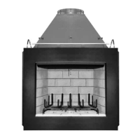
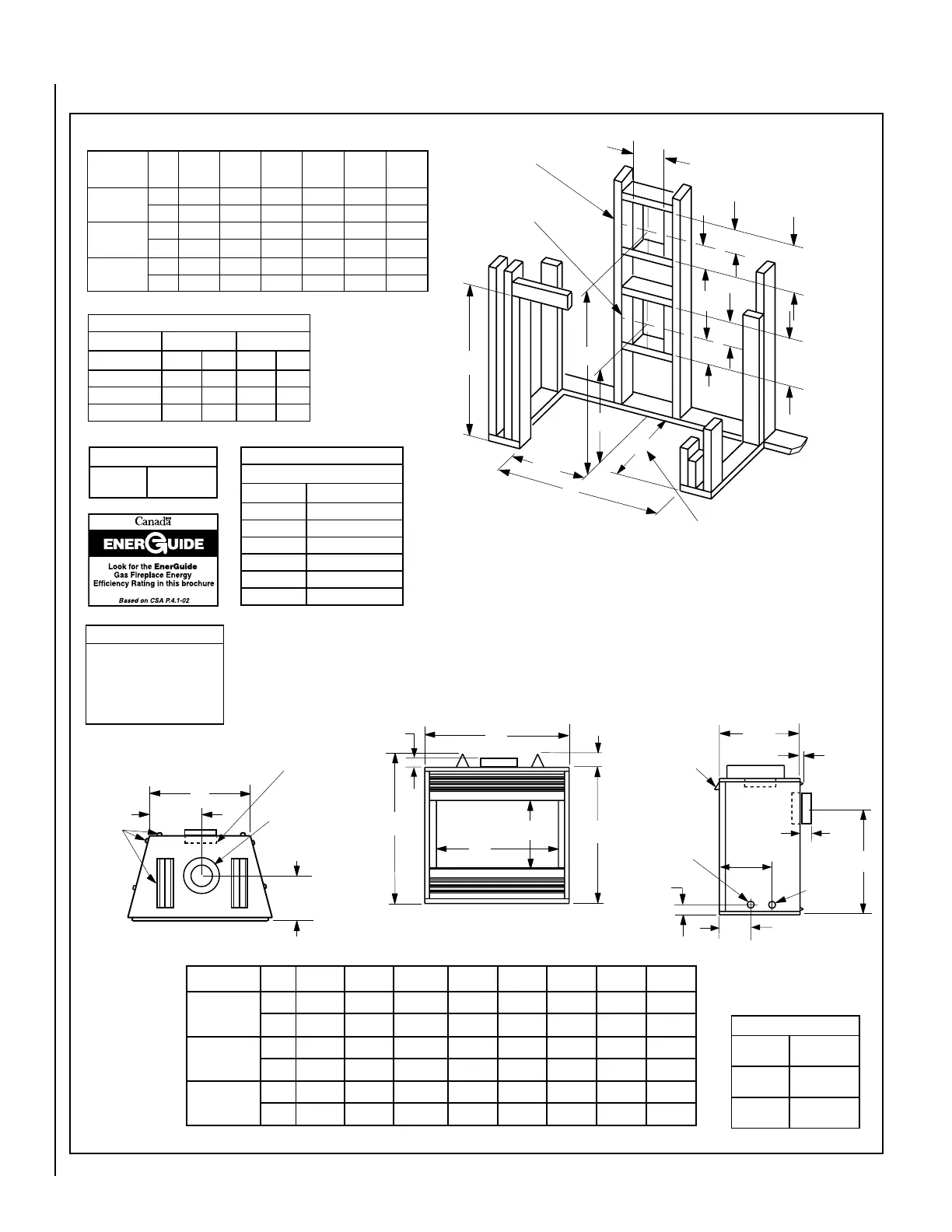
FIREPLACE AND FRAMING SPECIFICATIONS
Vent Size
Co-axial DV
Vent Size
4-1/2" Inner
7-1/2" Outer
Vertical Venting Through the Ceiling:
Frame ceiling opening - Use a plumb line from the ceiling above the appliance to
locate center of the vertical run. Cut and/or frame an opening, 10-1/2" x 10-1/2" (267
mm x 267 mm) inside dimensions, about this center mark (see Figure 18).
Notes
Diagrams, illustrations and photo-
graphs are not to scale – consult
installation instructions. Product
designs, materials, dimensions,
specifications, colors and prices are
subject to change or discontinuance
without notice.
Input (BTU/HR) - MV & Electronic
Natural & Propane Gas
Models Input Rate (BTU / HR)
EDV3530N 27,000
EDV3530P 27,000
EDV4035N 30,000
EDV4035P 30,000
EDV4540N 33,000
EDV4540P 33,000
Efficiencies %
Natural Gas Propane
Models AFUE P4 AFUE P4
EDV3530 63 61 64 61
EDV4035 64 64 64 65
EDV4540 65 63 66 62
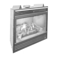
Viewable Glass Size
35" Model
29-1/2" Wide
24" High
40" Model
34-1/2" Wide
24" High
45" Model
39-1/2" Wide
24" High
Figure 13
Framing
.oNledoMFGHJKLMN
0353VDE
.ni8/1048/173422/1928/1532/1722/1124/301
mm9101349906947298896645372
5304VDE
.ni8/1048/173422/1438/1042/17222/164/331
mm91013499066789101896576733
0454VDE
.ni8/1048/173422/1938/1542/1722/1134/351
mm641134990630016411896208104
.oNledoMAB
C
RAER(
)TNEV
C
POT(
)TNEV
DE
0353VDE
.ni4/1534/1048/7028/5322/1724/364
mm69822010350069967811
5304VDE
.ni4/1044/1048/7028/5322/1724/364
mm220122010350069967811
0454VDE
.ni4/1544/1048/7028/5322/1724/364
mm941122010350069967811
A
B
E
7
(178)
5-1/8
12-1/8
(308)
10-1/2
(267)
D
VENT FRAMING -
TOP VENT WITH ONE
90° ELBOW
VENT FRAMING -
REAR VENT WITH
NO ELBOWS
Framing should be constructed
of 2x4 or larger lumber.
Inches (mm)
(130)
(130)
7
(308)
(178)
C is the required framing depth
dimension when the finish material
(drywall) thickness is 1/2 in. (13mm).
¹⁄₂ A
C
5-1/8
12-1/8
K
G
J
H
Front View
3 (76)
(Louvered Front Model Shown)
F
2
(51)
L
1/2 (13)
3 (76)
Right Side View
2-1/4
(57)
GAS INLET
(Either Side
and bottom)
ELECTRICAL
INLET
7
(179)
20-7/8
(531)
10-1/8
(257)
NOTE - Hood
shown as
positioned in
louvered front
model
M
N
Top View
REAR CONCENTRIC VENT
FLUE OUTLET - 4-1/2
(114), COMBUSTION AIR
- 7-1/2 (190)
10-7/8
(275)
TOP CONCENTRIC VENT
FLUE OUTLET - 4-1/2
(114), COMBUSTION
AIR - 7-1/2 (190)
FRAMING
SPACERS
(Top, Sides
and Rear)
 Loading...