32
NOTE: DIAGRAMS & ILLUSTRATIONS ARE NOT TO SCALE.
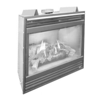
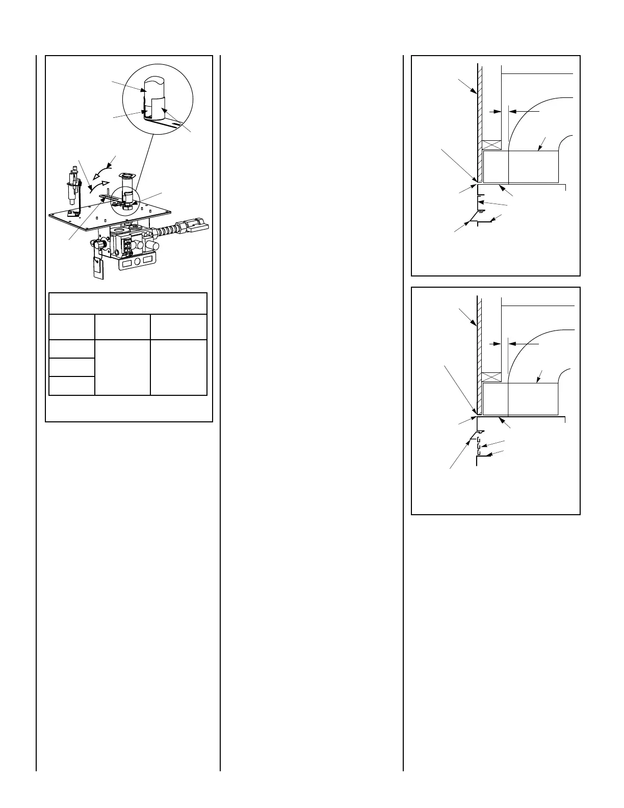
Figure 62
RENRUBNIAM
GNITTESGNINEPORETTUHSYROTCAFGNITTESGNINEPORETTUHSYROTCAF
GNITTESGNINEPORETTUHSYROTCAF
GNITTESGNINEPORETTUHSYROTCAFGNITTESGNINEPORETTUHSYROTCAF
sledoM
saGlarutaN
)mm(sehcni
saGenaporP
)mm(sehcni
0353VDE
8/1)2.3(8/3)5.9(5304VDE
0454VDE
Air Shutter
Opening
Burner
Venturi
Tube
Air
Shutter
Door
Orifice
Increase
Air Shutter
Opening
Decrease
Air Shutter
Opening
Air Shutter
Adjusting
Arm
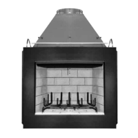
Combustible
Finished Wall
Materials
This Area Must Remain
Clear of Combustible
Materials
Top of Appliance
1" Min
(25 mm)
Spacer
Louver Face Models
Top of Door Frame
Combustible
material
may touch the
appliance top.
Hood must be installed as shown.
Louvers
Combustible
materials not
allowed below
this point on
the face of the
appliance.
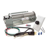
Combustible
Finished Wall
Materials
This Area Must Remain
Clear of Combustible
Materials
Top of Appliance
1" Min
(25 mm)
Spacer
Clean Face Models
Top of Door Frame
Hood must be installed as shown.
Radiant panel
Combustible
material
may touch the
appliance top.
Combustible
materials not
allowed below
this point on
the face of the
appliance.
Figure 63
Figure 64
Step 12. HOOD INSTALLATION
Refer to Figures 63 and 64. All of these
appliances must have hoods installed prior
to operating.
On all clean face units, slide the hood into the slots on
the lower edge of the radiant panel (Figure 63 ).
On louvered face units, slide the hood into the slots
on the lower edge of the cabinet top (Figure 64 ).
FINISHING REQUIREMENTS
- Wall Details
Complete finished interior wall. To install the
appliance facing flush with the finished wall, po-
sition framework to accommodate the thickness
of the finished wall (Figures 63 and 64 )
See Page 5 for
Cold Climate Insulation and
Page 8 for Clearances
 Loading...