Page 12
Filters
This unit is not equipped with a lter or rack. A eld-provid-
ed lter is required for the unit to operate properly. TABLE
3 lists recommended minimum lter size.
A lter must be in place whenever the unit is operating.
IMPORTANT
If a higheciency lter is being installed as part of this
system to ensure better indoor air quality, the lter must
be properly sized. Higheciency lters have a higher
static pressure drop than standardeciency glass/foam
lters. If the pressure drop is too great, system capacity
and performance may be reduced. The pressure drop
may also cause the limit to trip more frequently during
the winter and the indoor coil to freeze in the summer,
resulting in an increase in the number of service calls.
Before using any lter with this system, check the
specications provided by the lter manufacturer against
the data given in the appropriate Lennox Product
Specications bulletin. Additional information is provided
in Service and Application Note ACC002
(August 2000).
TABLE 3
Furnace Cabinet Width
Minimum Filter Size
16 x 25 x 1 (1)
17-1/2”
21”
Duct System
Use industry-approved standards to size and install the
supply and return air duct system. Refer to ACCA Manual
D. This will result in a quiet and low-static system that has
uniform air distribution. See FIGURE 19 for duct installa-
tion.
NOTE - This furnace is not certied for operation in heat-
ing mode (indoor blower operating at selected heating
speed) with an external static pressure which exceeds 0.8
inches w.c. Operation at these conditions may result in
improper limit operation.
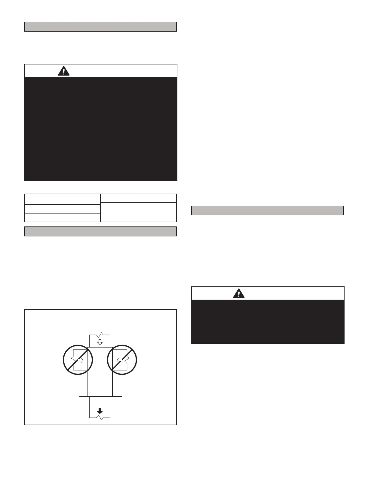
Duct Installation
Down-Flow Unit
SUPPLY
AIR
FIGURE 19
Supply Air Plenum
If the furnace is installed without a cooling coil, a remov-
able access panel should be installed in the supply air
duct. The access panel should be large enough to per-
mit inspection of the heat exchanger. The furnace access
panel must always be in place when the furnace is oper-
ating and it must not allow leaks into the supply air duct
system.
Return Air Plenum
NOTE - Return air must not be drawn from a room where
this furnace, or any other gas-fueled appliance (i.e., water
heater), or carbon monoxide-producing device (i.e., wood
replace) is installed.
When return air is drawn from a room, a negative pressure
is created in the room. If a gas appliance is operating in
a room with negative pressure, the ue products can be
pulled back down the vent pipe and into the room. This
reverse ow of the ue gas may result in incomplete com-
bustion and the formation of carbon monoxide gas. This
raw gas or toxic fumes might then be distributed through-
out the house by the furnace duct system.
Use berglass sealing strips, caulking, or equivalent seal-
ing method between the plenum and the furnace cabinet
to ensure a tight seal. If a lter is installed, size the return
air duct to t the lter frame.
Pipe & Fittings Specications
All pipe, ttings, primer and solvent cement must conform
with American National Standard Institute and the Ameri-
can Society for Testing and Materials (ANSI/ASTM) stan-
dards. The solvent shall be free owing and contain no
lumps, undissolved particles or any foreign matter that
adversely aects the joint strength or chemical resistance
of the cement. The cement shall show no gelation, strati-
cation, or separation that cannot be removed by stirring.
Refer to the table 4 below for approved piping and tting
materials.
CAUTION
Solvent cements for plastic pipe are ammable liquids
and should be kept away from all sources of ignition.
Do not use excessive amounts of solvent cement when
making joints. Good ventilation should be maintained to
reduce re hazard and to minimize breathing of solvent
vapors. Avoid contact of cement with skin and eyes.
 Loading...