Page 6
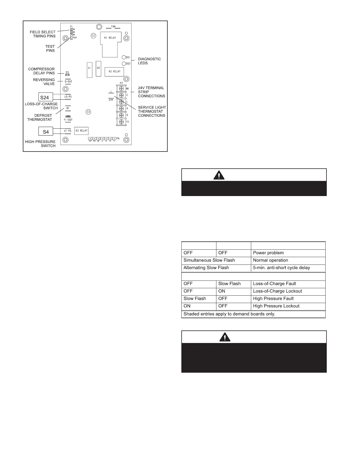
FIGURE 3
A TEST option is provided for troubleshooting. The TEST
mode may be started any time the unit is operating
in the heating mode and the defrost thermostat is
closed or jumpered. If the jumper is in the TEST position
at power-up, the control will ignore the test pins. When the
jumper is placed across the TEST pins for two seconds,
the control will enter the defrost mode. If the jumper is re-
moved before an additional 5-second period has elapsed
(7 seconds total), the unit will remain in defrost mode until
the defrost thermostat opens or 14 minutes have passed.
If the jumper is not removed until after the additional
5-second period has elapsed, the defrost will terminate
and the test option will not function again until the jumper
is removed and reapplied.
COMPRESSOR DELAY
The defrost board has a eld-selectable function to reduce
occasional sounds that may occur while the unit is cycling
in and out of the defrost mode. When the compressor de-
lay jumper is removed, the compressor will be cycled o
for 30 seconds going in and out of the defrost mode.
NOTE – The 30-second compressor feature is ignored
when jumper is installed on TEST pins.
TIME DELAY
The timed-o delay is ve minutes long. The delay helps
protect the compressor from short-cycling in case the
power to the unit is interrupted or a pressure switch opens.
The delay is bypassed by placing the timer select jumper
across the TEST pins for 0.5 seconds.
NOTE – The board must have a thermostat demand for
the bypass function.
PRESSURE SWITCH CIRCUITS
The defrost control includes two pressure switch circuits.
The factory-installed high pressure switch (S4) wires are
connected to the board’s HI PS terminals (gure 3). The
board also includes LO PS terminals to accommodate a
eld-provided low (or loss-of-charge) pressure switch.
During a single thermostat cycle, the defrost control will
lock out the unit after the fth time that the circuit is in-
terrupted by any pressure switch that is wired to the con-
trol board. In addition, the diagnostic LEDs will indicate
a pressure switch lockout after the fth occurrence of an
open pressure switch (see table 1). The unit will remain
locked out until power is broken then remade to the con-
trol or until the jumper is applied to the TEST pins for 0.5
seconds.
NOTE – The defrost control board ignores input from the
loss_of-charge switch terminals during the TEST mode,
during the defrost cycle, during the 90-second start-up
period, and for the rst 90 seconds each time the revers-
ing valve switches heat/cool modes. If the TEST pins are
jumpered and the 5-minute delay is being bypassed,
the LO PS terminal signal is not ignored during the
90-second start-up period.
SERVICE LIGHT CONNECTION
The defrost control board includes terminal connections
for a service light thermostat which provides a signal that
activates the room thermostat service light during periods
of inecient operation.
IMPORTANT
After testing has been completed, properly reposition
test jumper across desired timing pins
DIAGNOSTIC LEDS
The defrost board uses two LEDs for diagnostics. The
LEDs ash a specic sequence according to the diagno-
sis. See table 1.
TABLE 1
DS2 Green DS1 Red Condition
Fault and Lockout Codes
B-COOLING COMPONENTS
WARNING
Refrigerant can be harmful if it is inhaled. Refrigerant
must be used and recovered responsibly.
Failure to follow this warning may result in personal
injury or death.
1 - Compressor
ALL ELP model units use scroll compressors. Compressor
B1 operates during all cooling demand and is energized
by contactor K1 upon receiving demand. See ELECTRI-
CAL section or compressor nameplate for compressor
specications.
 Loading...