Page 7
SCROLL COMPRESSOR
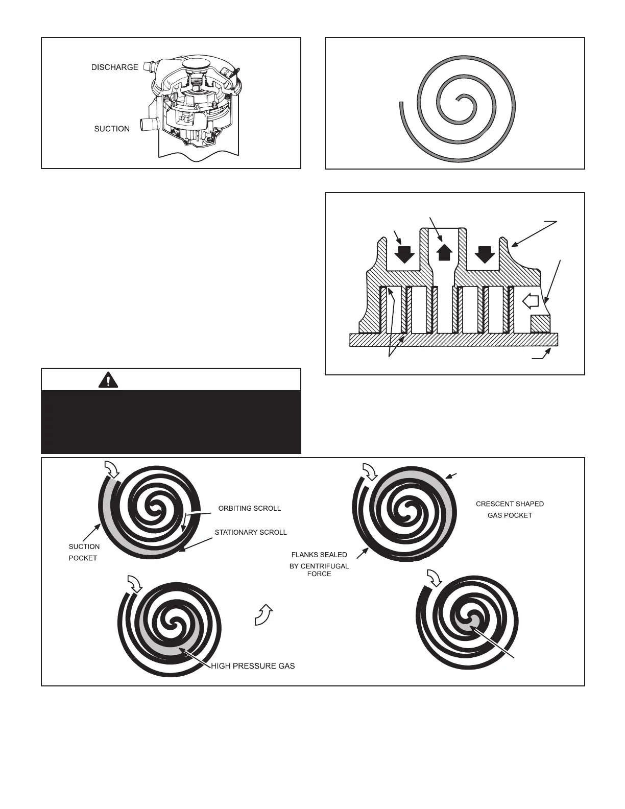
FIGURE 4
The scroll compressor design is simple, ecient and re-
quires few moving parts. A cutaway diagram of the scroll
compressor is shown in gure 4. The scrolls are located
in the top of the compressor can and the motor is located
just below. The oil level is immediately below the motor.
The scroll is a simple compression concept centered
around the unique spiral shape of the scroll and its in-
herent properties. Figure 5 shows the basic scroll form.
Two identical scrolls are mated together forming concen-
tric spiral shapes (gure 6). One scroll remains stationary,
while the other is allowed to ”orbit” (gure 7). Note that the
orbiting scroll does not rotate or turn but merely orbits the
stationary scroll.
NOTE – During operation, the head of a scroll compressor
may be hot since it is in constant contact with discharge gas.
IMPORTANT
Three-phase scroll compressor noise will be signicantly
higher if phasing is incorrect. Compressor will operate
in reverse, so unit will not provide cooling. If phasing is
incorrect, disconnect power to unit and reverse any two
power leads (L1 and L3 preferred) to unit.
SCROLL FORM
FIGURE 5
STATIONARY SCROLL
ORBITING SCROLL
DISCHARGE
SUCTION
CROSS-SECTION OF SCROLLS
TIPS SEALED BY
DISCHARGE
PRESSURE
FIGURE 6
1
2
3
4
SUCTION
SUCTION
SUCTION
DISCHARGE
POCKET
SUCTION
INTERMEDIATE PRESSURE
GAS
MOVEMENT OF ORBIT
FIGURE 7
 Loading...