Page 8
The counterclockwise orbiting scroll draws gas into the
outer crescent shaped gas pocket created by the two
scrolls (gure 7- 1). The centrifugal action of the orbiting
scroll seals o the anks of the scrolls (gure7-2). As the
orbiting motion continues, the gas is forced toward the
center of the scroll and the gas pocket becomes com-
pressed (gure 7- 3). When the compressed gas reaches
the center, it is discharged vertically into a chamber and
discharge port in the top of the compressor (gure 6). The
discharge pressure forcing down on the top scroll helps
seal o the upper and lower edges (tips) of the scrolls (g-
ure 6). During a single orbit, several pockets of gas are
compressed simultaneously providing smooth continuous
compression.
The scroll compressor is tolerant to the eects of liquid
return. If liquid enters the scrolls, the orbiting scroll is al-
lowed to separate from the stationary scroll. The liquid is
worked toward the center of the scroll and is discharged. If
the compressor is replaced, conventional Lennox cleanup
practices must be used.
Due to its eciency, the scroll compressor is capable of
drawing a much deeper vacuum than reciprocating com-
pressors. Deep vacuum operation can cause internal
fusite arcing resulting in damaged internal parts and will
result in compressor failure. Never use a scroll compres-
sor for evacuating or “pumping-down” the system. This
type of damage can be detected and will result in denial of
warranty claims.
The scroll compressor is quieter than a reciprocating com-
pressor, however, the two compressors have much dier-
ent sound characteristics. The sounds made by a scroll
compressor do not aect system reliability, performance,
or indicate damage.
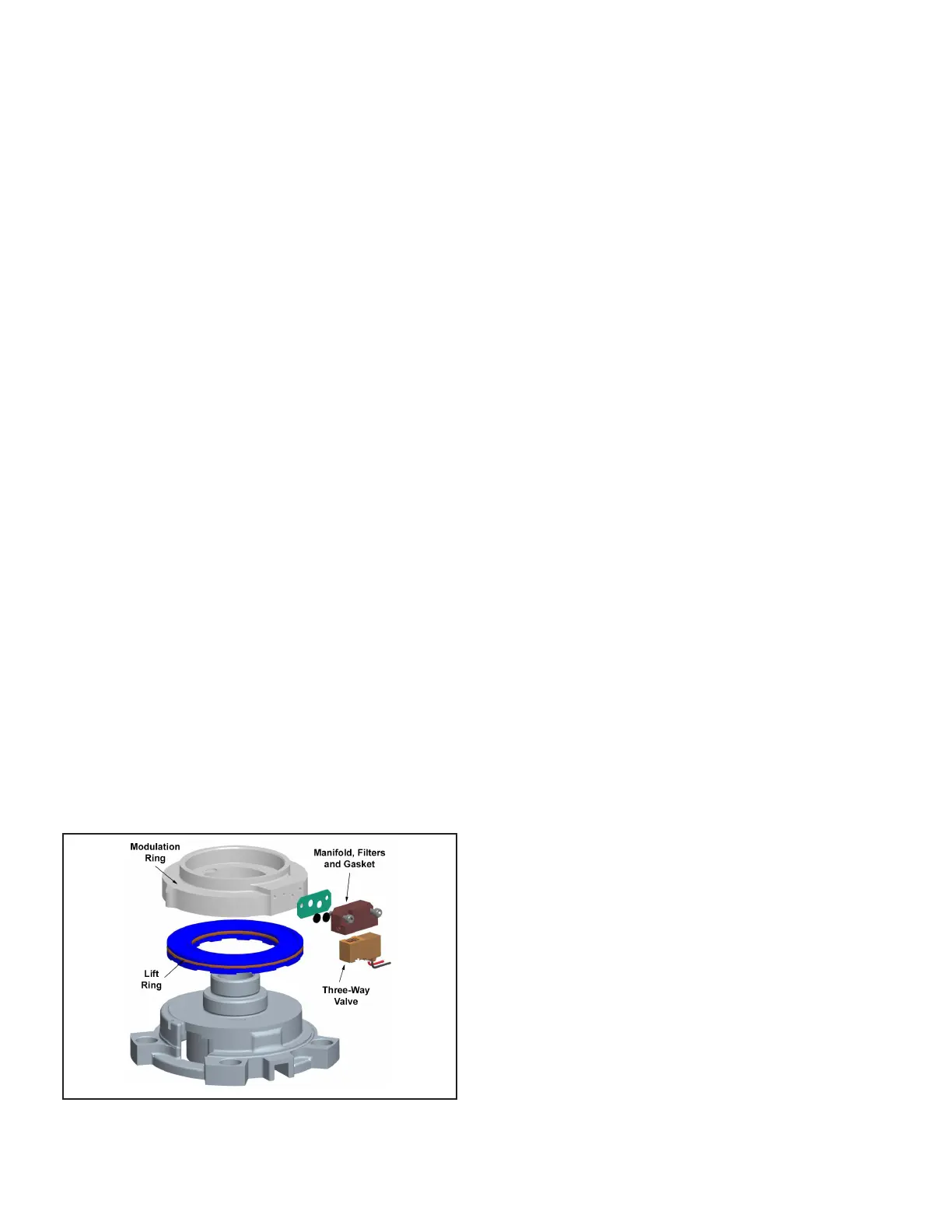
A 24-volt DC solenoid valve inside the compressor controls
staging. When the 3-way solenoid is energized it moves
the lift ring assembly to block the ports and the compressor
operates at full-load or 100% capacity. When the solenoid
is de-energized the lift ring assembly moves to unblock the
compressor ports and the compressor operates at part-
load or approximately 67% of its full-load capacity.
The “loading” and “unloading” of the two stage scroll is
done “on the y” without shutting o the single-speed
compressor motor between stages.
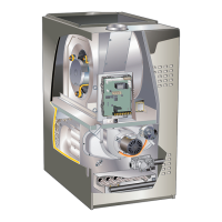
FIGURE 8. Two-Stage Scroll Compressor
2 - Two Stage Compressor Solenoid (L34) Resistance
Check
Resistance check: Measure the resistance from the end
of one molded plug lead to either of the two female con-
nectors in the plug. One of the connectors should read
close to zero ohms while the other should read innity.
Repeat with other wire. The same female connector as
before should read zero while the other connector again
reads innity. Reverse polarity on the ohmmeter leads and
repeat. The female connector that read innity previously
should now read close to zero ohms. Replace plug if ei-
ther of these test methods don’t show the desired results.
3 - Crankcase Heater HR1 (all units)
All ELP series units use a belly-band type crankcase heat-
er. Heater HR1 is wrapped around compressor B1. HR1
assures proper compressor lubrication at all times.
4 - High Pressure Switch S4
The high pressure switch is a auto-reset SPST N.C. switch
which opens on a pressure rise. The switch is located on the
compressor discharge line and is wired to the defrost control
board CMC1. When discharge pressure rises to 450 ± 10
psig (3103 ± 69 kPa) the switch opens and the compressor is
de-energized through the CMC1. The switch will close when
discharge pressure drops to 300 ± 20 psig (2068 ± 138 kPA).
5 - Low Pressure Switch (S87)
The loss-of-charge switch is a auto-reset SPST N.C. switch
which opens on a pressure drop. The switch is located on
the suction line and is wired to the defrost control board
CMC1. When suction line pressure drops to 40 psi the switch
opens and the compressor is de-energized through the
CMC1. The switch will close when pressure rises to 90 psi.
6 - Filter Drier (all units)
All ELP model units have a lter drier that is located in the
liquid line of each refrigerant circuit at the exit of each con-
denser coil. The drier removes contaminants and moisture
from the system.
7 - Reversing Valve L1 (all units)
A reversing valve with an electromechanical solenoid is
used to reverse refrigerant ow during unit operation. L1 is
energized during cooling demand and defrost. See gures
on page 4.
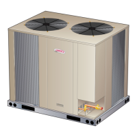
8 - Condensor Fans B4 and B5
See page 2 for the specications on the condenser fans
used in the ELP units. All condenser fans have single-
phase motors. The ELP090/120 units are equipped with
two condenser fans. The fan assembly may be removed
for servicing by removing the motor mounts nuts.
II- REFRIGERANT SYSTEM
A-Plumbing
Field refrigerant piping consists of liquid and vapor lines
from the outdoor unit (sweat connections) to the indoor
evaporator coil (sweat connections). Refer to table 2 for
eld-fabricated refrigerant line sizes. Refer to Lennox Re-
frigerant Piping manual Corp. #9351-L9 for proper size,
type and application of eld-fabricated lines. Separate dis-
charge and suction service ports are provided at the com-
pressor for connection of gauge manifold during charging
procedure.
 Loading...