15
PRESSURE AIR DROP = 15 Pa.
PRESSURE WATER DROP = 20K Pa
DATA CALCULATED FOR AIR FLOW = 1100 m
3
/h
PRESSURE AIR DROP =
20 Pa.
PRESSURE WATER DROP =
40 kPa
DATA CALCULATED FOR AIR FLOW =
2000 m
3
/h
PRESSURE AIR DROP =
13 Pa.
PRESSURE WATER DROP =
50 kPa
DATA CALCULATED FOR AIR FLOW =
2500 m
3
/h
PRESSURE AIR DROP =
18 Pa.
PRESSURE WATER DROP =
50 kPa
DATA CALCULATED FOR AIR FLOW =
3500 m
3
/h
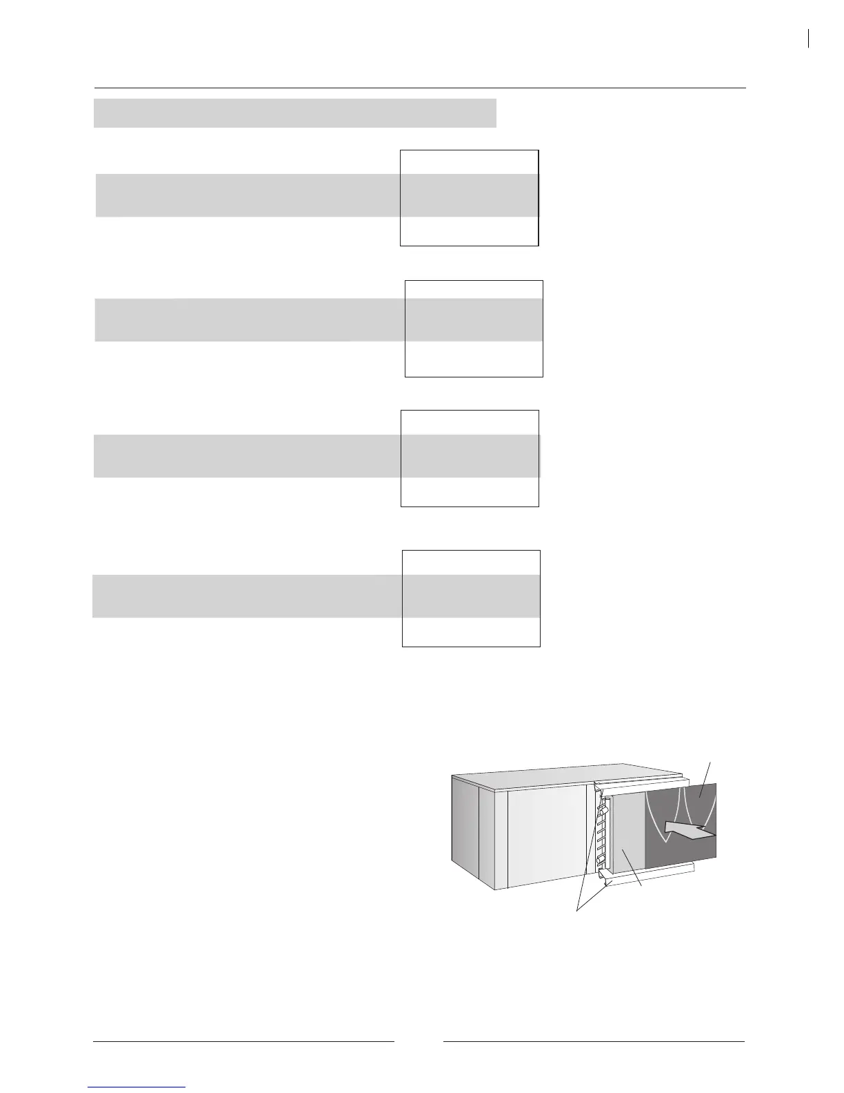
Hot water coil
Attachment profiles
THREE PHASE PROTECTION (THREE PHASE UNITS)
Located at the electrical box of the unit, it assures that unit will not begin operation if connection phases of compressor are
not correct. Should this occur, then just switch two phase connections.
COMPRESSOR ACOUSTIC JACKET
Each compressor is fitted with a compressor acoustic jacket this provides attenuation of the compressor noise that radiates
from the unit when in operation.
HOT WATER COIL 1 ROW TECHNICAL DATA
(for cooling only units).
OPTIONS
FWCK/FWHK 12-16
FWCK/FWHK 08-10
FWCK/FWHK 04-06-07
CAPACITY IN kW FOR WATER FLOW OF 250 L/H .
60
50
40
DIFFERENCES BETWEEN WATER INLET
TEMPERATURE AND COIL AIR INLET
TEMPERATURE (ºC)
5,10 4,25 3,40
CAPACITY IN kW FOR WATER FLOW OF
350 L/H .
60
50
40
7,70 6,50 5,20
CAPACITY IN kW FOR WATER FLOW OF
600 L/H .
60
50
40
12,40 10,30 8,30
FWCK/FWHK 22
CAPACITY IN kW FOR WATER FLOW OF
600 L/H .
60
50
40
13,60 11,30 9,00
DIFFERENCES BETWEEN WATER INLET
TEMPERATURE AND COIL AIR INLET
TEMPERATURE (ºC)
DIFFERENCES BETWEEN WATER INLET
TEMPERATURE AND COIL AIR INLET
TEMPERATURE (ºC)
DIFFERENCES BETWEEN WATER INLET
TEMPERATURE AND COIL AIR INLET
TEMPERATURE (ºC)
This option kit includes a hot water coil with two attachment
profiles for coil to the unit.
Make sure to install the hot water coil to the aspiration of
the unit, then:
• Dismount the air filter attachment.
• Fix the attachment profiles with screws to the
aspiration.
• Fix the hot water coil to the attachment profiles.
• Put the air filter again across the profiles.
Air filter
INSTALLATION
 Loading...