16
5 kW 1 Step
6 kW 1 Step
9 kW 1 Step
9 kW 1 Step
12 kW 1 Step
3 kW 1 Step
UNIT
Water exchanger
Valve spindle
of regulation
Connect to high
pressure plug
Presostatic
valve
Flow switch
Water filter
WATER INLET
WATER OUTLET
NOTE:
Install one of then.
You can not use both
in the same unit.
ELECTRICAL HEATER
WATER FILTER
This option is supplied loose.
The water filter must be fitted in the water
inlet of the unit, it protects the unit against
particles (greater than 1 mm) getting
inside the water circuit, and prevents the
water interchanger gets dirty.
With water filter water pressure drop
has a different value (see table page 8).
FLOW SWITCH
This option is supplied loose.
It should be used for heat pump units
(FWHK).
The flow switch stops the unit if water
flow is lower than the nominal.
Electrical reset.
MAIN SWITCH (Not available for 04/06/07 models)
The main switch is equipped with a gadget, which allows opening the panel of the electrical box, when it is on OFF position.
Verify that the main switch is large enough to handle the current for the unit.
OPTIONS
Power
230 V 1Ph -50Hz
FWCK/FWHK 06-07
FWCK/FWHK
08-10
FWCK/FWHK
12-16-22
230 V /400 V 3Ph -50Hz
230 V /400 V 3Ph -50Hz
Voltage
FWCK/FWHK 04
230 V 1Ph -50Hz
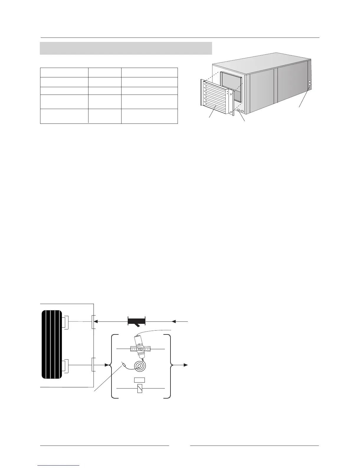
INSTALLATION
• The electrical heater should be installed into the impulsion fan of the unit.
• Fix the electrical heater to the unit with the screws (see the figure above).
• Take out the knock out, and take the electrical supply of the electrical heater to the electrical box of the unit. There is a different
power supply for electrical heater (see page 4).
PRESOSTATIC VALVE (only for units FWCK)
This option is supplied loose.
If water inlet temperature is below 15ºC use a pressostatic valve to keep adequate condensation temperature levels (40º to
45ºC).
The maximum inlet water temperature with this option is 35ºC.
PRESSOSTATIC VALVES REGULATION
• Connect a manometer of high pressure (30 bar) in the refrigerant circuit.
• Turn over the spindle in the head of the valve (turn right: the valve is opened; turn left: the valve is closed) regulating the water
flow which enters into the unit.
• You must leave the unit working at least 10 minutes and see the indication of the manometer. If the condensation pressure
temperature is approximately 45ºC, the valve is correctly regulated. If not, restart the regulation as described before.
INSTALLATION
• Replace the outlet pipe of the plate exchanger inside the unit for a pressostatic valve.
• Keep in mind the row direction indicated in the valve.
• Connect the capillary tube of the valve to the plug of high pressure in the pipe of the unit.
OPERATION
The pressostatic valve keeps the condensation pressure values regulating the inlet water flow in the condenser.
When the condensation pressure is up, the valve will be opened, and more water is entered. And when the pressure is low
the valve will be closed.
Electrical heater
Knock out
Electrical box
 Loading...