Page 29
8 −Disconnect gas supply piping. Remove four screws se-
curing the burner manifold assembly to the vestibule
panel and remove the assembly from the unit.
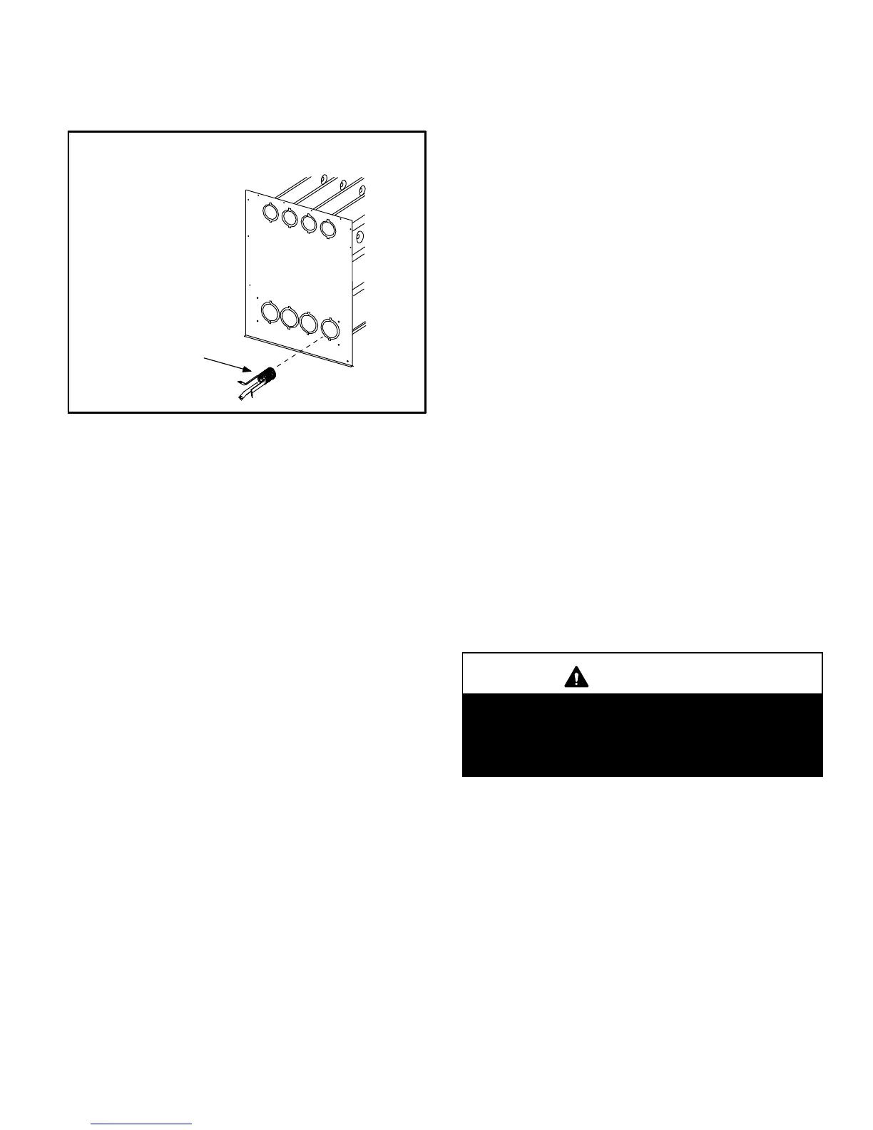
NO
x
INSERTS
(X models only)
FIGURE 28
NO
x
INSERT
9 −NOx units only − Remove the three screws that attach
the NO
x
insert to the corbel at the entrance to each
heat exchanger section. Carefully remove the NO
x
in-
sert from each section. See figure 28.
10 −Insert the brush end of cable snake into the top of one
of the heat exchanger openings. Do not force the
cable into the heat exchanger. Insert the cable and
operate the drill on slow speed. Move the cable in and
out of the heat exchanger section three or four times or
until sufficient cleaning is accomplished. Reverse drill
and slowly work the cable out of opening.
11 −Repeat procedure for each heat exchanger section.
12 −After each of the top heat exchanger sections has
been cleaned, insert the brush end of the cable snake
into the bottom openings of each of the heat exchanger
sections and clean as described in step 8.
13 −Remove the cable from the heat exchanger. Use a
vacuum cleaner to remove debris knocked loose dur-
ing cleaning.
14 −Attach the exhaust end (positive pressure) of the vacu-
um cleaner to the top of the heat exchanger section.
Any loose debris will be forced to the bottom of the heat
exchanger section. Vacuum debris from bottom open-
ings.
15 −Replace collector box and combustion air inducer.
Check gaskets for damage. Damaged gaskets must
be replaced to avoid heat exchanger leaks. Replace all
screws to the collector box and combustion air inducer.
Failure to replace all screws may cause leaks.
16 −To clean the burner, run a vacuum cleaner with a soft
brush attachment over the face of burners. Inspect in-
side the burners and crossovers for any blockage.
Clean the inside of the burner if necessary.
17 −Label and disconnect the pressure switch wires.
18 −Remove the four screws that secure the combustion
air inducer. Carefully remove the combustion air induc-
er to avoid damaging the blower gasket. If the gasket is
damaged, it must be replaced to prevent leakage. See
figure 27.
19 −NO
x
Units − Reattach the NO
x
inserts to the corbels at
the entrance to each heat exchanger opening. See fig-
ure 28.
20 −Reinstall the burner/manifold assembly on the vesti-
bule panel.
21 −Reconnect wires to pressure switch, roll−out switches,
gas valve and combustion air inducer. Refer to unit wir-
ing diagram.
22 −Use screws to resecure the junction box to the cabinet.
23 −Apply RTV/high temperature silicone sealant between
the internal flue pipe and the combustion air inducer.
24 −Use one screw to resecure the internal flue pipe to the
combustion air inducer.
25 −Use three screws to resecure the vent pipe to the flue
collar. See figure 10.
26 −Reconnect the gas supply piping.
27 −Turn on power and gas supply to the unit.
28 −Set thermostat and check for proper operation.
29 −Check all piping connections, factory and field, for gas
leaks. Use a leak detecting solution or other preferred
means.
CAUTION
Some soaps used for leak detection are corrosive to
certain metals. Carefully rinse piping thoroughly af-
ter leak test has been completed. Do not use
matches, candles, flame or other sources of ignition
to check for gas leaks.
30 −If a leak is detected, shut gas and electricity off and re-
pair leak.
31 −Repeat steps 35 and 36 until no leaks are detected.
32 −Replace front access panels.
 Loading...


