Page 9
2 − After opening is cut, set additive base into opening.
3 − Check fiberglass strips on additive base to make sure
they are properly glued and positioned.
4 − Lower supply air plenum into additive base until ple-
num flanges seal against fiberglass strips.
NOTE − Be careful not to damage fiberglass strips.
Check for a tight seal.
5 − Set the furnace over the plenum.
6 − Ensure that the seal between the furnace and plenum
is adequate.
G40DF(X)UNIT
SUPPLY AIR PLENUM
ADDITIVE BASE
PROPERLY
SIZED FLOOR
OPENING
FIGURE 6
Installation on Cooling Cabinet
1 − Refer to reverse−flow coil installation instructions for
correctly sized opening in floor and installation of cabi-
net.
2 − When cooling cabinet is in place, set and secure the
furnace according to the instructions that are provided
with the cooling coil. Secure the furnace to the cabinet.
3 − Seal the cabinet and check for air leaks.
Return Air Opening −− Downflow Units
The following steps should be taken when installing ple-
num:
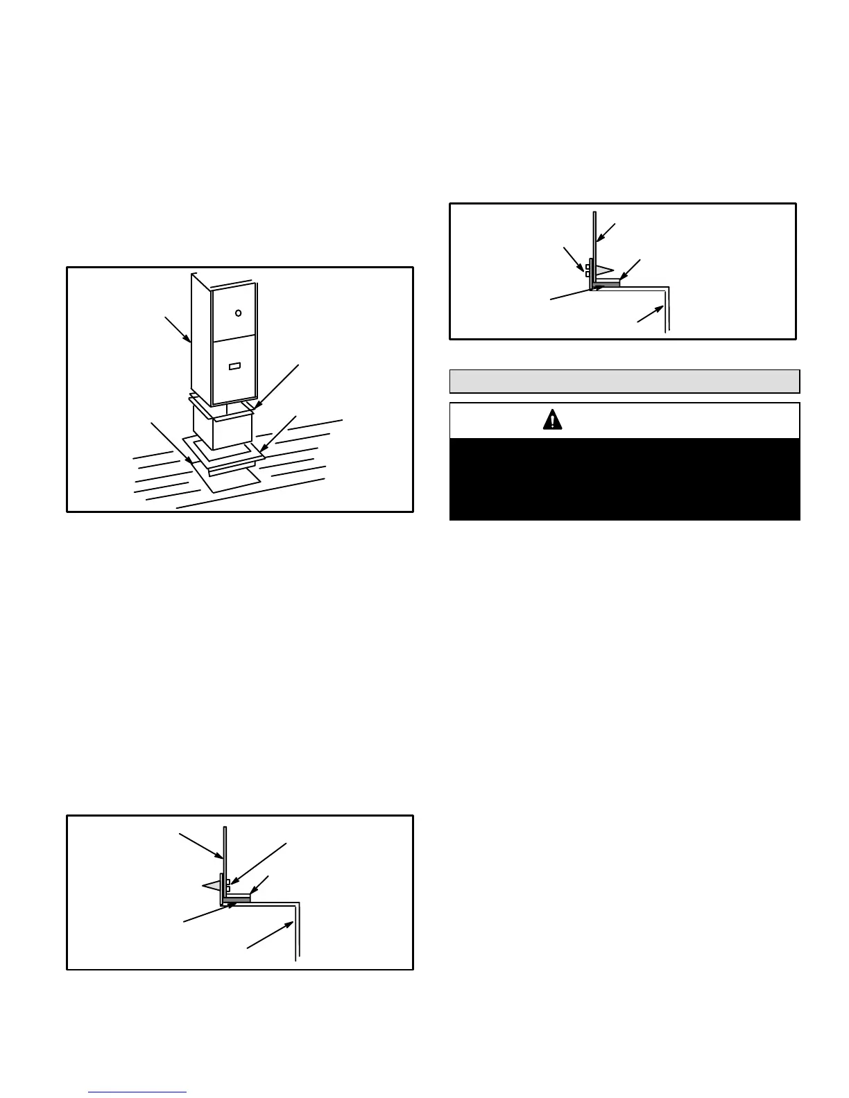
1 − Bottom edge of plenum should be flanged with a
hemmed edge (See figure 7).
2 − Fiberglass sealing strips should be used.
SECURE FROM
OUTSIDE CABINET
HEMMED EDGE
PLENUM
FIBERGLASS SEALING
STRIP
(Field Provided)
CABINET SIDE PANEL
Side View
FIGURE 7
3 − In all cases, plenum should be secured to top flanges
of furnace with sheet metal screws.
4 − In closet installations, it may be impossible to install
sheet metal screws from the outside. In this case,
make plenum with a removable front and install
screws from the inside (See figure 8).
5 − Make certain that an adequate seal is made.
SECURE FROM
INSIDE CABINET
HEMMED EDGE
FIBERGLASS
SEALING STRIP
(Field Provided)
CABINET SIDE
PANEL
PLENUM
Side View
FIGURE 8
Setting Equipment
WARNING
Do not install the furnace on its front or its back. Do
not connect the return air ducts to the back of the fur-
nace. Doing so will adversely affect the operation of
the safety control devices, which could result in per-
sonal injury or death.
Install the G40DF(X) gas furnace as shipped. Do not
install the furnace horizontally.
Select a location that allows for the required clearances
that are listed on the unit nameplate. Also consider gas
supply connections, electrical supply, vent connection,
and installation and service clearances [24 inches (610
mm) at unit front]. The unit must be level.
NOTE − 1/3 hp blower motors are equipped with four flex-
ible mounting legs, and 1/2 hp blower motors are equipped
with three flexible legs and one rigid leg. The rigid leg is
equipped with a shipping bolt and a flat white plastic wash-
er (rather than the rubber mounting grommet used with a
flexible mounting leg). The bolt and washer must be re-
moved before the furnace is placed into operation. Af-
ter the bolt and washer have been removed, the rigid leg
will not touch the blower housing.
NOTE − G40DF−36C−110 units include a bracket which sta-
bilizes the blower motor during shipping. The bracket is se-
cured to the blower housing by two screws. This bracket
must be removed prior to placing the unit into opera-
tion. See figure 1.
Downflow Application
Allow for clearances to combustible materials as indi-
cated on the unit nameplate. Minimum clearances for
closet or alcove installations are shown in figure 9.
 Loading...


