Page 8
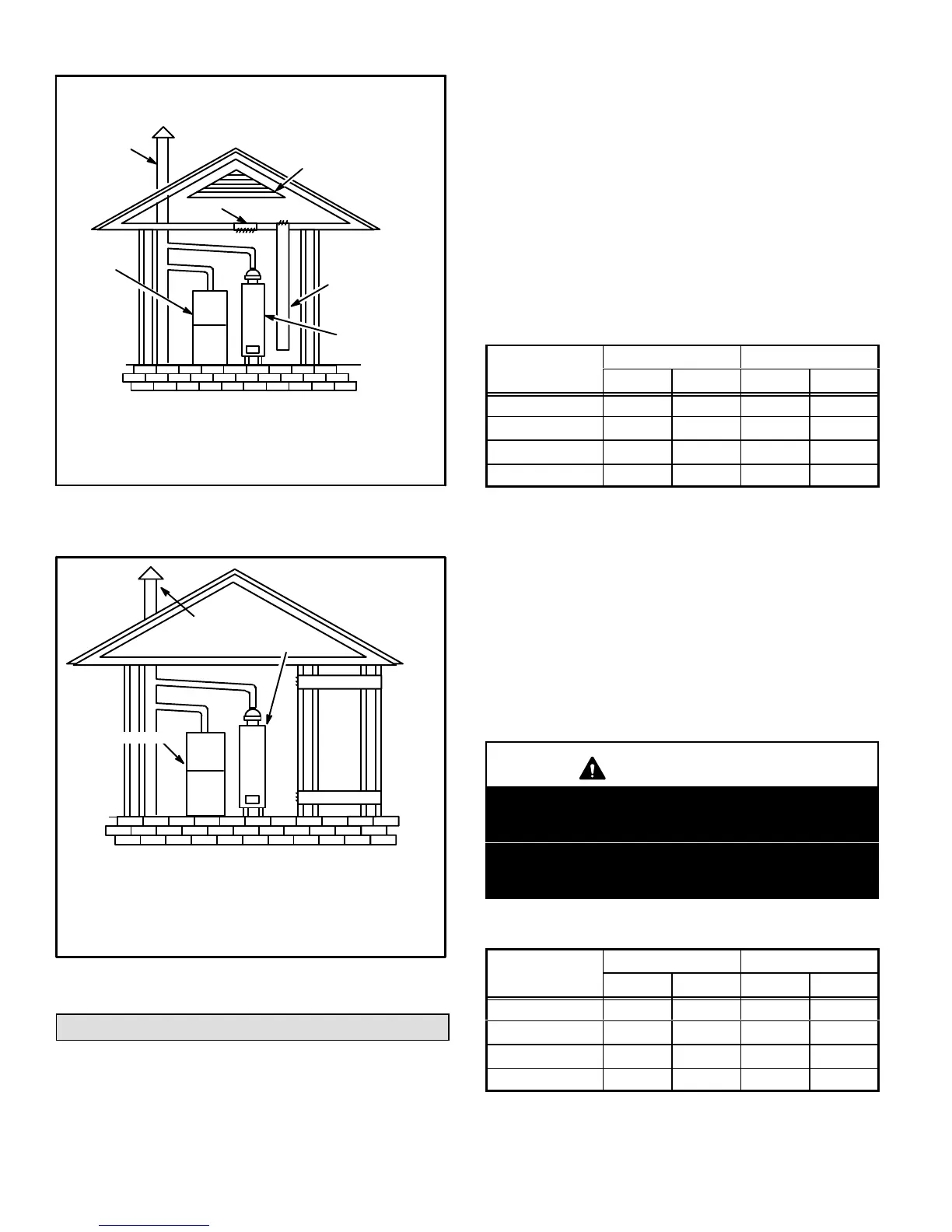
EQUIPMENT IN CONFINED SPACE
ALL AIR FROM OUTSIDE
(All Air Through Ventilated Attic)
NOTE−The inlet and outlet air openings shall each have a
free area of at least one square inch (645 mm
2
) per 4,000
Btu (1.17 kW) per hour of the total input rating of all equip-
ment in the enclosure.
CHIMNEY
OR GAS
VENT
WATER
HEATER
OUTLET
AIR
VENTILATION LOUVERS
(Each end of attic)
INLET AIR
(Ends 12 in.
above bottom)
FURNACE
FIGURE 4
EQUIPMENT IN
CONFINED SPACE
ALL AIR FROM
OUTSIDE
OUTLET AIR
INLET AIR
WATER
HEATER
CHIMNEY
OR GAS
VENT
NOTE − Each air duct opening shall have a free area of at least
one square inch (645 mm
2
) per 2,000 Btu (.59 kW) per hour of
the total input rating of all equipment in the enclosure. If the
equipment room is located against an outside wall and the air
openings communicate directly with the outdoors, each open-
ing shall have a free area of at least one square inch (645 mm
2
)
per 4,000 Btu (1.17 kW) per hour of the total input rating of all
other equipment in the enclosure.
FURNACE
FIGURE 5
Downflow Installation
Downflow unit installs in three ways: on noncombustible
flooring, on combustible flooring using an additive base, or
on a reverse−flow cooling cabinet. Do not drag the unit
across the floor.
Installation on Noncombustible Flooring
1 − Cut floor opening keeping in mind clearances listed on
unit rating plate. Also keep in mind gas supply connec-
tions, electrical supply, flue and air intake connections
and sufficient installation and servicing clearances.
See table 1 for correct floor opening size.
2 − Flange warm air plenum and lower the plenum into the
opening.
3 − Set the unit over the plenum and seal the plenum to
the unit.
3 − Ensure that the seal is adequate.
TABLE 1
NONCOMBUSTIBLE FLOOR OPENING SIZE
Model No.
Front to Rear Side to Side
in. mm in. mm
A Cabinet (14.5") 19 − 3/4 502 13 − 1/4 337
B Cabinet (17.5") 19 − 3/4 502 16 − 1/4 413
C Cabinet (21") 19 − 3/4 502 19 − 3/4 502
D Cabinet (24.5") 19 − 3/4 502 23 − 1/4 591
NOTE − Floor opening dimensions listed are 1/4 inch (6 mm) larger than
the unit opening. See figure 1.
Installation on Combustible Flooring
1 − When unit is installed on a combustible floor, an addi-
tive base must be installed between the furnace and
the floor. The base must be ordered separately for the
following cabinet sizes:
D A cabinet 14.5" − # 11M59
D B cabinet 17.5" − # 11M60
D C cabinet 21" − # 11M61
D D cabinet 24.5" − # 11M62
See table 2 for opening size to cut in floor.
CAUTION
The furnace and additive base shall not be installed
directly on carpeting, tile, or other combustible ma-
terial other than wood flooring.
The furnace and additive base shall not be installed
directly on carpeting, tile, or other combustible ma-
terial other than wood flooring.
TABLE 2
ADDITIVE BASE FLOOR OPENING SIZE
Model No.
Front to Rear Side to Side
in. mm in. mm
A Cabinet (14.5")
22 559 15 − 3/4 400
B Cabinet (17.5")
22 559 18 − 3/4 476
C Cabinet (21")
22 559 22 − 3/4 578
D Cabinet (24.5")
22 559 25 − 3/4 654
NOTE − Floor opening dimensions listed are 1/4 inch (6 mm) larger than
unit opening. See figure 1.
 Loading...


