Page 20
Resize the common venting system to the minimum
size determined by using the appropriate tables in ap-
pendix G. (These are in the current standards of the
National Fuel Gas Code ANSI Z223.1 in the USA, and
the appropriate Category 1 Natural Gas and Propane
appliances venting sizing tables in the current stan-
dards of the CSA B149 Natural Gas and Propane
Installation Codes in Canada.)
Gas Piping
CAUTION
If a flexible gas connector is required or allowed by
the authority that has jurisdiction, black iron pipe
shall be installed at the gas valve and extend outside
the furnace cabinet.
WARNING
Do not exceed 600 in−lbs (50 ft−lbs) torque when at-
taching the gas piping to the gas valve.
Gas Supply
1 − This unit is shipped standard for left or right side instal-
lation of gas piping (or top entry in horizontal applica-
tions). Connect the gas supply to the piping assembly.
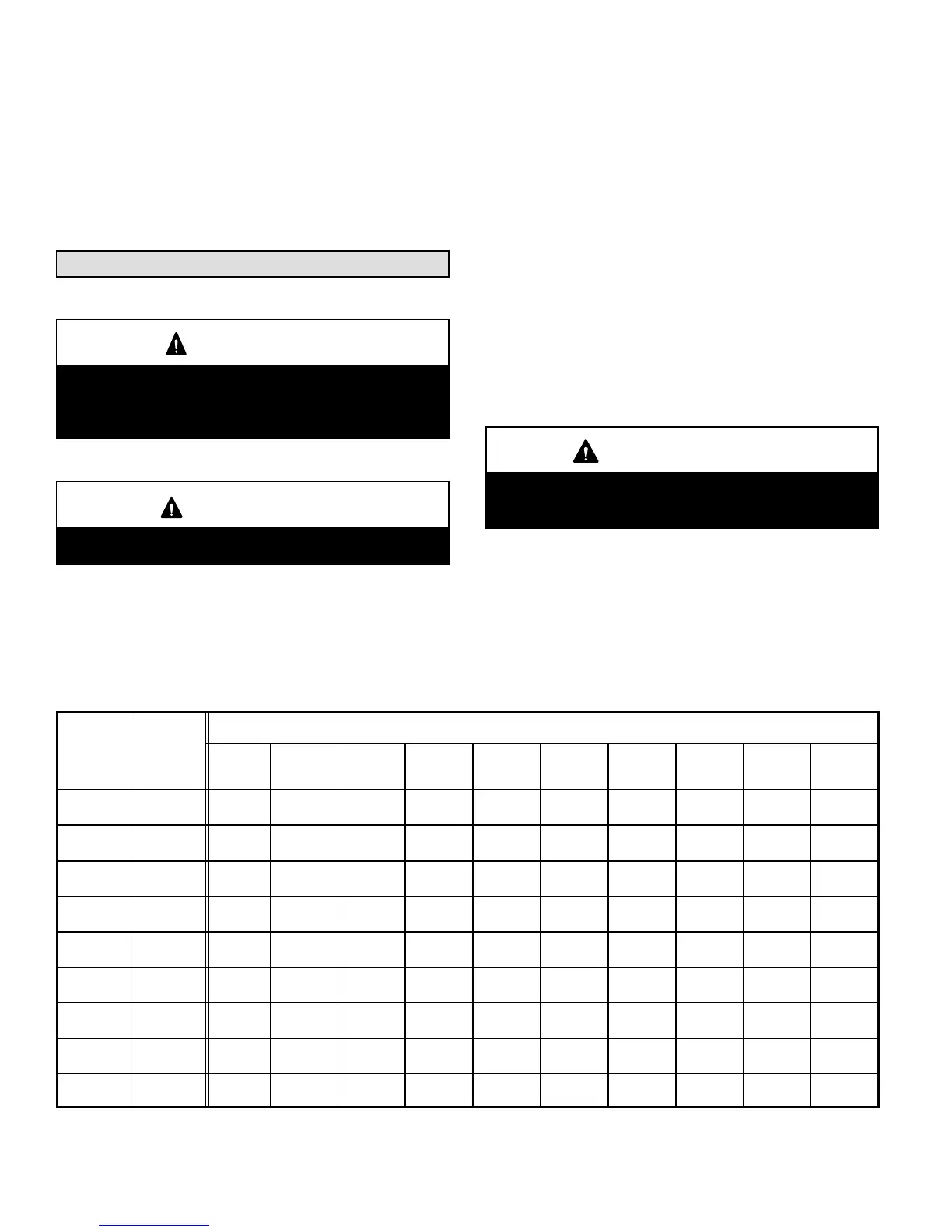
2 − When connecting the gas supply piping, consider fac-
tors such as length of run, number of fittings, and fur-
nace rating to avoid excessive pressure drop. Table 9
lists recommended pipe sizes for typical applications.
3 − The gas piping must not run in or through air ducts,
clothes chutes, gas vents or chimneys, dumb waiters,
or elevator shafts.
4 − The piping should be sloped 1/4 inch (6.4 mm) per 15
feet (4.57 m) upward toward the meter from the fur-
nace. The piping must be supported at proper intervals
[every 8 to 10 feet (2.44 to 3.01 m)] with suitable hang-
ers or straps. Install a drip leg inside vertical pipe runs
to the unit.
5 − In some localities, codes may require the installation of
a manual main shut-off valve and union (furnished by
the installer) external to the unit. The union must be of
the ground joint type.
IMPORTANT
Compounds used on threaded joints of gas piping
must be resistant to the actions of liquified petro-
leum gases.
NOTE − Install a 1/8 inch NPT plugged tap in the field piping
upstream of the gas supply connection to the unit. The tap
must be accessible for test gauge connection. See figure 19.
NOTE − If emergency shutoff is necessary, shut off the main
manual gas valve and disconnect main power to the fur-
nace. The installer should properly label these devices.
TABLE 9
Gas Pipe Capacity − ft
3
/hr (m
3
/hr)
Nominal
Iron Pi
e
Internal
Length of Pipe − feet (m)
Size
inches
(mm)
Diameter
inches
(mm)
10
(3.048)
20
(6.096)
30
(9.144)
40
(12.192)
50
(15.240)
60
(18.288)
70
(21.336)
80
(24.384)
90
(27.432)
100
(30.480)
3/8
(9.53)
.493
(12.522)
95
(2.69)
65
(1.84)
52
(1.47)
45
(1.27)
40
(1.13)
36
(1.02)
33
(.73)
31
(.88)
29
(.82)
27
(.76)
1/2
(12.7)
.622
(17.799)
175
(4.96)
120
(3.40)
97
(2.75)
82
(2.32)
73
(2.07)
66
(1.87)
61
(1.73)
57
(1.61)
53
(1.50)
50
(1.42)
3/4
(19.05)
.824
(20.930)
360
(10.19)
250
(7.08)
200
(5.66)
170
(4.81)
151
(4.28)
138
(3.91)
125
(3.54)
118
(3.34)
110
(3.11)
103
(2.92)
1
(25.4)
1.049
(26.645)
680
(919.25)
465
(13.17)
375
(10.62)
320
(9.06)
285
(8.07)
260
(7.36)
240
(6.80)
220
(6.23)
205
(5.80)
195
(5.52)
1−1/4
(31.75)
1.380
(35.052)
1400
(39.64)
950
(26.90)
770
(21.80)
660
(18.69)
580
(16.42)
530
(15.01)
490
(13.87)
460
(13.03)
430
(12.18)
400
(11.33)
1−1/2
(38.1)
1.610
(40.894)
2100
(59.46)
460
(41.34)
1180
(33.41)
990
(28.03)
900
(25.48)
810
(22.94)
750
(21.24)
690
(19.54)
650
(18.41)
620
(17.56)
2
(50.8)
2.067
(52.502)
3950
(111.85)
2750
(77.87)
2200
(62.30)
1900
(53.80)
1680
(47.57)
1520
(43.04)
1400
(39.64)
1300
(36.81)
1220
(34.55)
1150
(32.56)
2−1/2
(63.5)
2.469
(67.713)
6300
(178.39)
4350
(123.17)
3520
(99.67)
3000
(84.95
2650
(75.04)
2400
(67.96)
2250
(63.71)
2050
(58.05)
1950
(55.22)
1850
(52.38)
3
(76.2)
3.068
(77.927)
11000
(311.48)
7700
(218.03)
6250
(176.98)
5300
(150.07)
4750
(134.50)
4300
(121.76)
3900
(110.43)
3700
(104.77)
3450
(97.69)
3250
(92.03)
NOTE − Capacity given in cubic feet (m
3
) of gas per hour and based on 0.60 specific gravity gas.
 Loading...


