Page 27
Gas Pressure
1 − Check the gas line pressure with the unit firing at maxi-
mum rate. A minimum of 4.5 in. w.c. for natural gas or
11.0 in. w.c. for LP/propane gas should be maintained.
2 − After the line pressure has been checked and ad-
justed, check the manifold pressure. A natural gas to
LP/propane gas changeover kit is required to convert
the unit. Manifold pressure for all units is given in table
11. See figures 27, 28 and 29 for the location of the
manifold pressure adjustment screws.
High Altitude Information
NOTE − In Canada, certification for installations at eleva-
tions over 4500 feet (1372 m) is the jurisdiction of local au-
thorities.
The manifold pressure may require adjustment to ensure
proper operation at higher altitudes. See table 11 for proper
manifold pressure settings at varying altitudes.
TABLE 11
Manifold Pressure (Outlet) inches w.c.
Altitude (feet)
Fuel
0−4500 4501−5500 5501−6500 6501−7500
Nat.
Gas
3.5 3.3 3.2 3.1
L.P.
Gas
10.0 10.0 10.0 10.0
NOTE − A natural to L.P. propane gas changeover kit is nec-
essary to convert this unit. L.P. conversion kit 45L60 is used
with all units installed at altitudes up to 7,500 feet. L.P. con-
version kit 47M81 is used with all units installed at altitudes
from 7,501 to 10,000 feet above sea level. Refer to the
changeover kit installation instruction for the conversion
procedure.
NOTE − Units fueled by natural gas and installed at alti-
tudes of 7501−10,000 feet above sea level require installa-
tion of a high altitude orifice kit (47M82).
The combustion air pressure switches are factory−set and
require no adjustment. Table 12 lists the replacement pres-
sure switch required for G40UH(X) units installed at alti-
tudes above 4,500 feet above sea level.
TABLE 12
Altitude (feet)
Model
4501−7500
Pres. Switch
Replacement
Required
7501−10000
Pres. Switch
Replacement
Required
G40UH(X)−045−070 56L32 56L32
G40UH(X)−090−110 49L90 15M22
G40UH(X)−135−155 49L90 15M22
Other Unit Adjustments
Primary and Secondary Limits
The primary limit is located on the heating compartment
vestibule panel. The secondary limits (if equipped) are lo-
cated in the blower compartment, attached to the back side
of the blower. These limits are factory set and require no
adjustment.
Flame Rollout Switches (Two)
These manually reset switches are located on (or inside of)
the burner box. If tripped, check for adequate combustion
air before resetting.
Pressure Switch
The pressure switch is located in the heating compartment
adjacent to the combustion air inducer. This switch checks
for proper combustion air inducer operation before allow-
ing ignition trial. The switch is factory−set and requires no
adjustment.
Temperature Rise
Place the unit into operation with a heating demand. After
supply and return air temperatures have stabilized, check
the temperature rise. If necessary, adjust the blower speed
to maintain the temperature rise within the range shown on
the unit nameplate. Increase the blower speed to decrease
the temperature rise. Decrease the blower speed to in-
crease the temperature rise. Failure to adjust the tempera-
ture rise may cause erratic limit operation.
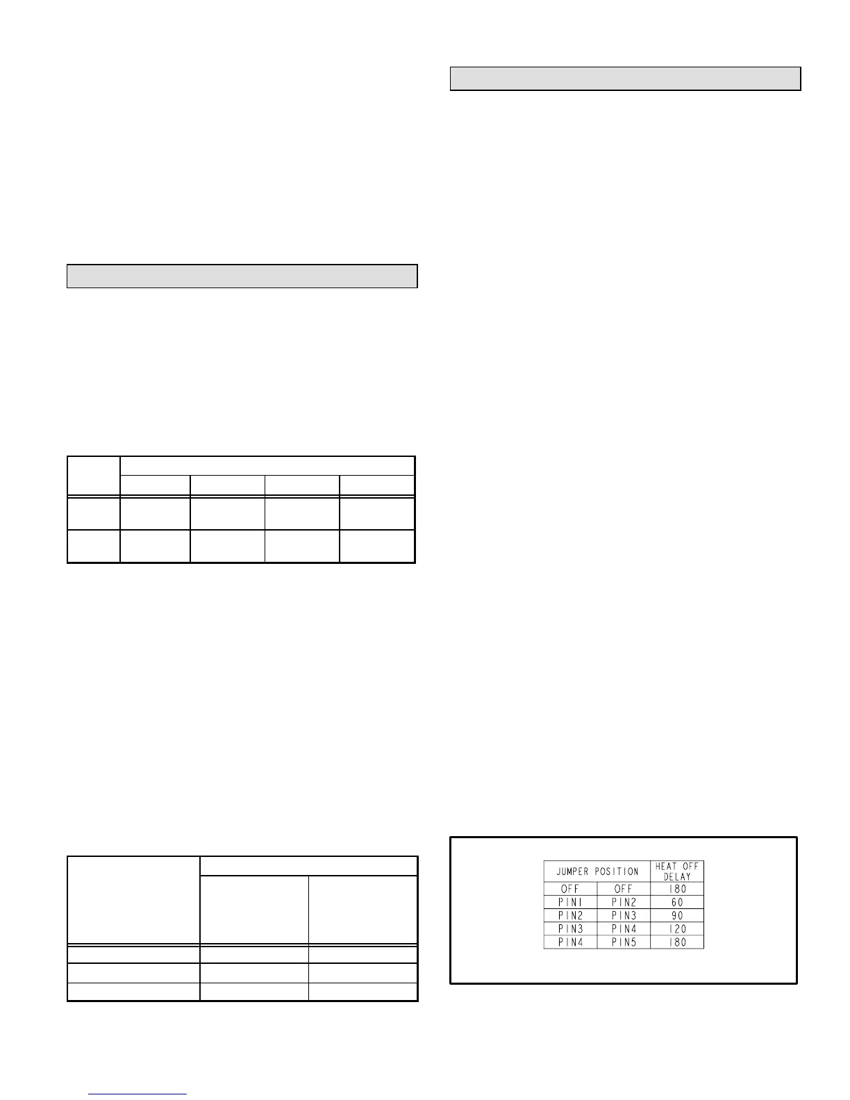
Fan Control
There is no cooling mode fan on delay; however, there is a
cooling fan off delay of 45 seconds. This delay is not adjust-
able.
The heating mode fan on delay of 45 seconds is not adjust-
able. The heating mode fan off delay (amount of time that
the blower operates after the heat demand has been satis-
fied) may be adjusted by changing the jumper position
across the five pins on the integrated control. The unit is
shipped with a factory fan off setting of 90 seconds. The fan
off delay affects comfort and is adjustable to satisfy individ-
ual applications. Adjust the fan off delay to achieve a supply
air temperature between 90° and 110°F at the exact mo-
ment that the blower is de−energized. Longer off delay set-
tings provide lower return air temperatures; shorter set-
tings provide higher return air temperatures. See figure 30.
FAN-OFF TIME ADJUSTMENT
To adjust fan−off timing, reposition jumper across pins to
achieve desired setting.
FIGURE 30
 Loading...


