Page 19
4. Integrated Ignition Control (A92)
78M47 & 100973−01
WARNING
Shock hazard.
Disconnect power before servicing. Control is
not field repairable. If control is inoperable, sim-
ply replace entire control.
Can cause injury or death. Unsafe operation will
result if repair is attempted.
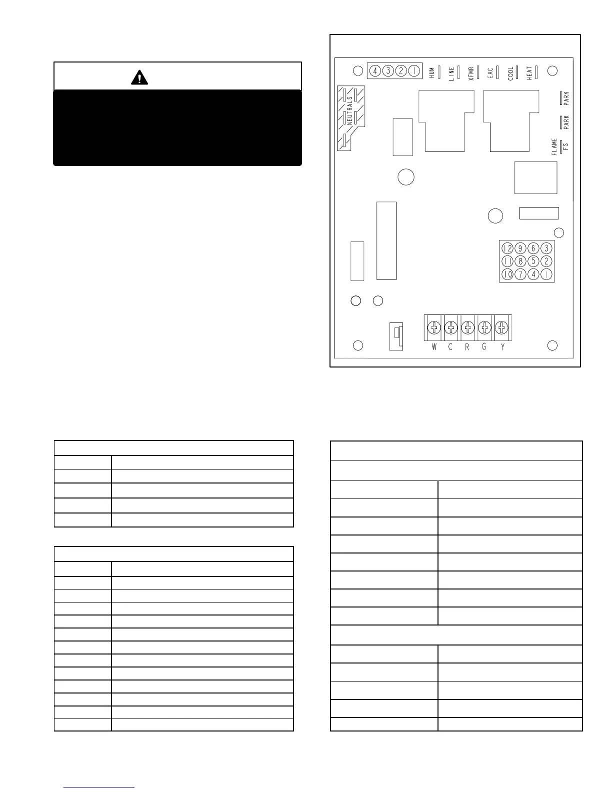
The hot surface ignition control system consisting of an in-
tegrated control board (figure 8 with control terminal des-
ignations in table 7), sensor (figure 10) and ignitor (figure
11). The ignition control board and ignitor work in com-
bination to ensure furnace ignition and ignitor durability.
The ignition control, controls all major furnace operations.
The ignition control also features two LED lights (AN1 red
and AN2 green) for troubleshooting and two accessory
terminals rated at (1) one amp. The ignition control also
features a (3) amp fuse for overcurrent protection. Tables 5
and 6 show jack plug terminal designations. See table 4 for
troubleshooting diagnostic codes. The mini−nitride ignitor
is made from a non−porous, high strength proprietary ce-
ramic material that provides long life and trouble free
maintenance. The ignition control continuously monitors
line voltage and maintains the ignitor power at a consis-
tent level to provide proper lighting and maximum ignitor
life.
TABLE 5
4−Pin Terminal Designation
PIN # FUNCTION
1 Combustion Air Inducer Line
2
Ignitor Line
3
Combustion Air Inducer Neutral
4
Ignitor Neutral
TABLE 6
12−Pin Terminal Designations
PIN # FUNCTION
1 High Limit Output
2 Not Used
3 24V Line
4 Not Used
5 Rollout Switch Out
6 24V Neutral
7 High Limit Input
8 Ground
9 Gas Valve Common
10 Prove Switch In
11 Rollout Switch In
12 Gas Valve Out
INTEGRATED IGNITION CONTROL
FIGURE 8
AN2
GREEN
AN1
RED
TABLE 7
TERMINAL DESIGNATIONS
120 Volt Hot
COOL Cool Speed
HEAT Heat Speed
PARK Park
PARK Park
EAC Electronic Air Cleaner
XFMR Transformer
LINE Line
HUM Humidifier
120 Volt Neutral
CIRC Blower
XMFR Transformer
HUM Humidifier
LINE Line
Flame FS Flame Signal
 Loading...


