Page 23
12.Gas Valve Figures 16, 15, 17 & 18
The G40UH(X) uses a gas valve manufactured by Honey-
well or White Rodgers. The valve is internally redundant to
assure safety shut−off. If the gas valve must be replaced,
the same type valve must be used.
24VAC terminals and gas control knob or switch are located
on the valve. All terminals on the gas valve are connected to
wires from the electronic ignition control. 24V applied to the ter-
minals energizes the valve.
Inlet and outlet pressure taps are located on the valve. A regu-
lator adjustment screw is located on the valve.
LPG changeover kits are available from Lennox. Kit s include
burner orifices and a gas valve regulator conversion kit.
FIGURE 15
WHITE RODGERS 36F Series Gas Valve
GAS VALVE SHOWN IN OFF POSITION
MANIFOLD
PRESSURE
ADJUSTMENT
SCREW
MANIFOLD
PRESSURE
OUTLET
WHITE RODGERS 36E SERIES GAS VALVE
GAS VALVE SHOWN IN OFF POSITION
MANIFOLD
PRESSURE
ADJUSTMENT
SCREW
MANIFOLD
PRESSURE
OUTLET
FIGURE 16
ON
OFF
HONEYWELL VR8205 SERIES GAS VALVE
GAS VALVE SHOWN IN OFF POSITION
MANIFOLD
PRESSURE
ADJUSTMENT
SCREW
MANIFOLD
PRESSURE
OUTLET
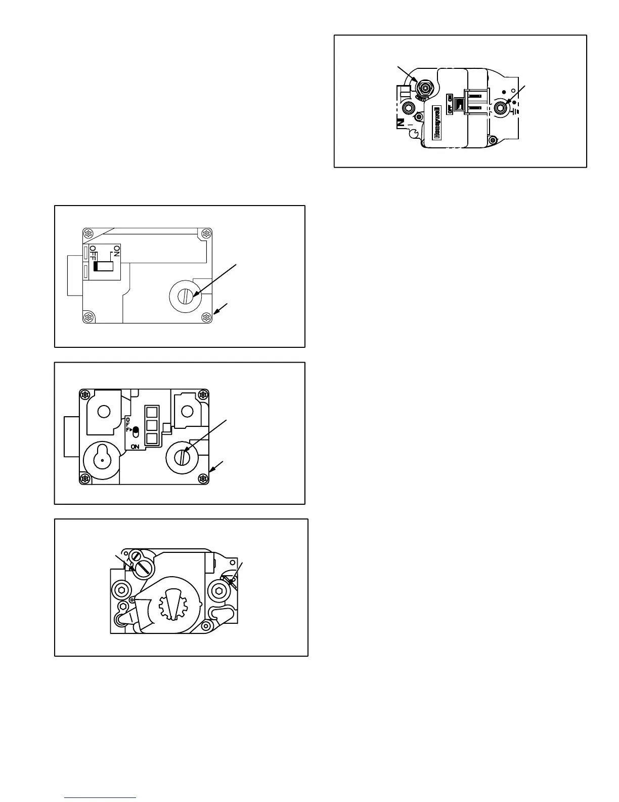
FIGURE 17
HONEYWELL VR8205 SERIES GAS VALVE
(With On/Off Switch)
GAS VALVE ON/OFF SWITCH SHOWN IN ON POSITION
MANIFOLD
PRESSURE
OUTLET
MANIFOLD
PRESSURE
ADJUSTMENT
SCREW
(under cap)
FIGURE 18
13.Combustion Air Inducer
Proving Switch (S18)
G40UH(X) series units are equipped with a combustion air
proving switch located on the combustion air inducer orifice
bracket. The switch is connected to the combustion air in-
ducer housing by means of a flexible silicone hose. It moni-
tors negative air pressure in the combustion air inducer
housing.
The switch is a single-pole single-throw proving switch elec-
trically connected to the furnace control. The purpose of the
switch is to prevent burner operation if the combustion air in-
ducer is not operating or if the flue becomes obstructed.
On start-up, the switch senses that the combustion air in-
ducer is operating. It closes a circuit to the furnace control
when pressure inside the combustion air inducer de-
creases to a certain set point. Set points vary depending on
unit size. See table 11. The pressure sensed by the switch
is negative relative to atmospheric pressure. If the flue be-
comes obstructed during operation, the switch senses a
loss of negative pressure (pressure becomes more equal
with atmospheric pressure) and opens the circuit to the fur-
nace control and gas valve. A bleed port on the switch al-
lows relatively dry air in the vestibule to purge switch tub-
ing, to prevent condensate build up.
The switch is factory set and is not field adjustable. It is a
safety shut-down control in the furnace and must not be by−
passed for any reason. If switch is closed or by−passed, the
control will not initiate ignition at start up.
 Loading...


