Page 27
G50UH Series
8 − Honeywell VR8205 Gas Valve with ON/OFF Switch −
Move gas valve switch to ON. See figure 27.
Honeywell VR8205 Gas Valve with Control Knob −
Turn knob on gas valve counterclockwise
to ON.
Do not force. See figure 28.
White Rodgers 36G Gas Valve − Move gas valve
switch to ON. See figure 29.
9 − Replace the upper access panel.
10− Turn on all electrical power to to the unit.
11− Set the thermostat to desired setting.
NOTE − When unit is initially started, steps 1 through 11
may need to be repeated to purge air from gas line.
12− If the appliance will not operate, follow the instructions
Turning Off Gas to Unit" and the gas supplier.
Turning Off Gas to Unit
1 − Set the thermostat to the lowest setting.
2 − Turn off all electrical power to the unit if service is to be
performed.
3 − Remove the upper access panel.
4 − Honeywell VR8205 Gas Valve with ON/OFF Switch −
Move gas valve switch to OFF. See figure 27.
Honeywell VR8205 Gas Valve with Control Knob −
Turn knob on gas valve clockwise
to OFF. Do not
force. See figure 28.
White Rodgers 36G Gas Valve − Move gas valve
switch to OFF. See figure 29.
5 − Replace the upper access panel.
Heating Sequence Of Operation
1 − When thermostat calls for heat, combustion air inducer
starts.
2 − Combustion air pressure switch proves combustion air
inducer operation. Switch is factory set and requires no
adjustment.
3 − After a 15 second prepurge, the hot surface ignitor en-
ergizes.
4 − After a 20 second ignitor warm−up period, the gas
valve solenoid opens.
5 − Gas is ignited, flame sensor proves the flame, and the
combustion process continues.
6 − If flame is not detected after first ignition trial, the igni-
tion control will repeat steps 3 and 4 four more times
before locking out the gas valve (WATCHGUARD"
flame failure mode). The ignition control will then auto-
matically repeat steps 3, 4, 5, and 6 after 60 minutes.
7 − To interrupt the 60−minute WATCHGUARD" period,
move thermostat from Heat" to OFF" then back to
Heat". Heating sequence then restarts at step 1.
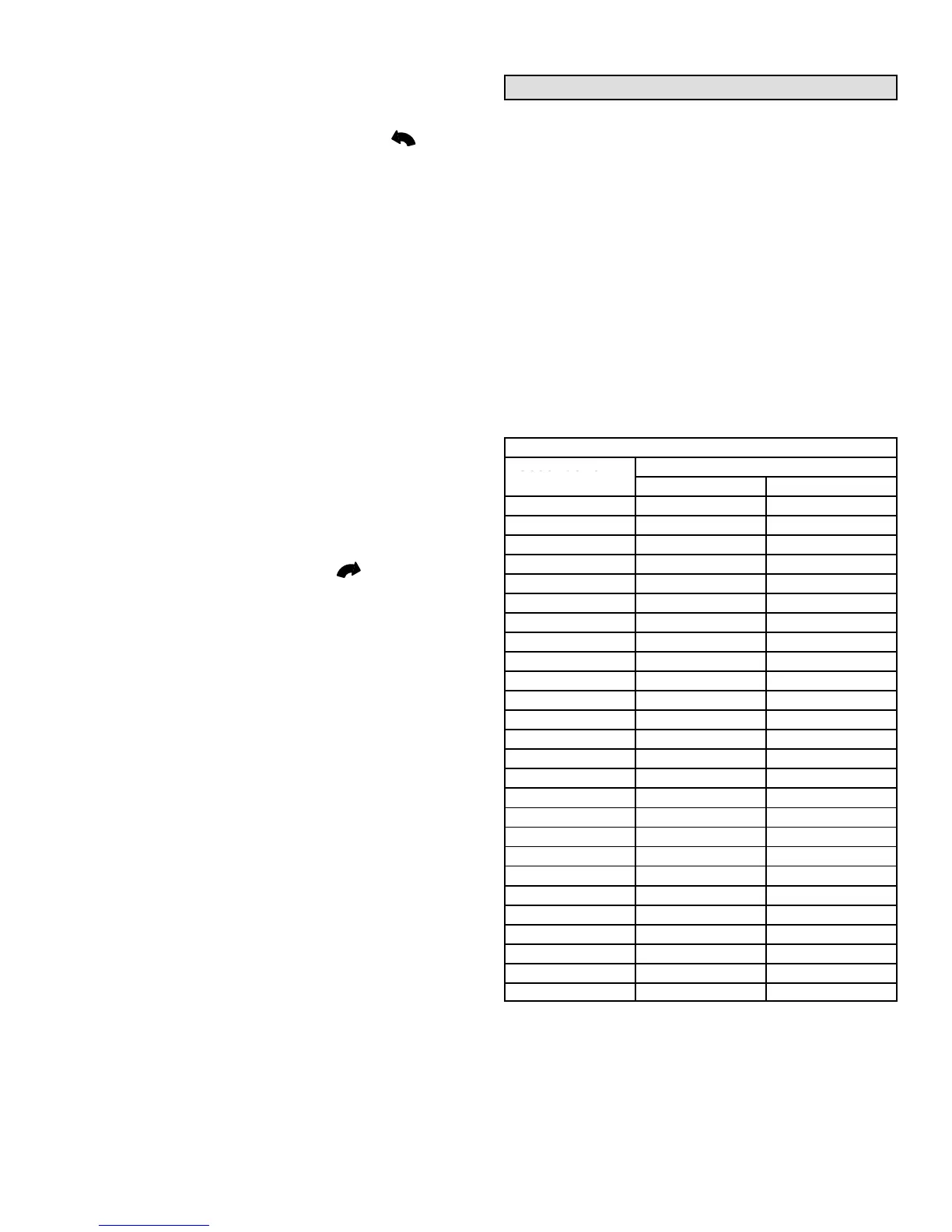
Gas Pressure Adjustment
Gas Flow (Approximate)
1 − Operate unit at least 15 minutes before checking gas
flow. Determine the time in seconds for one revolu-
tions of gas through the meter. A portable LP gas me-
ter (17Y44) is available for LP applications.
2 − Compare the number of seconds and the gas meter
size in table 10 to determine the gas flow rate. Multiply
the gas flow rate by the heating value to determine the
unit input rate. If manifold pressure is correct and the
unit input rate is incorrect, check gas orifices for proper
size and restriction.
3 − Remove temporary gas meter if installed.
NOTE − To obtain accurate reading, shut off all other gas
appliances connected to meter.
TABLE 10
Gas Flow Rate (Ft.
3
/Hr.)
Seconds for 1
Gas Meter Size
 Loading...