Page 34
505254M 05/2009
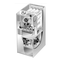
NOx INSERTS
(X models only)
FIGURE 31
NOx INSERT
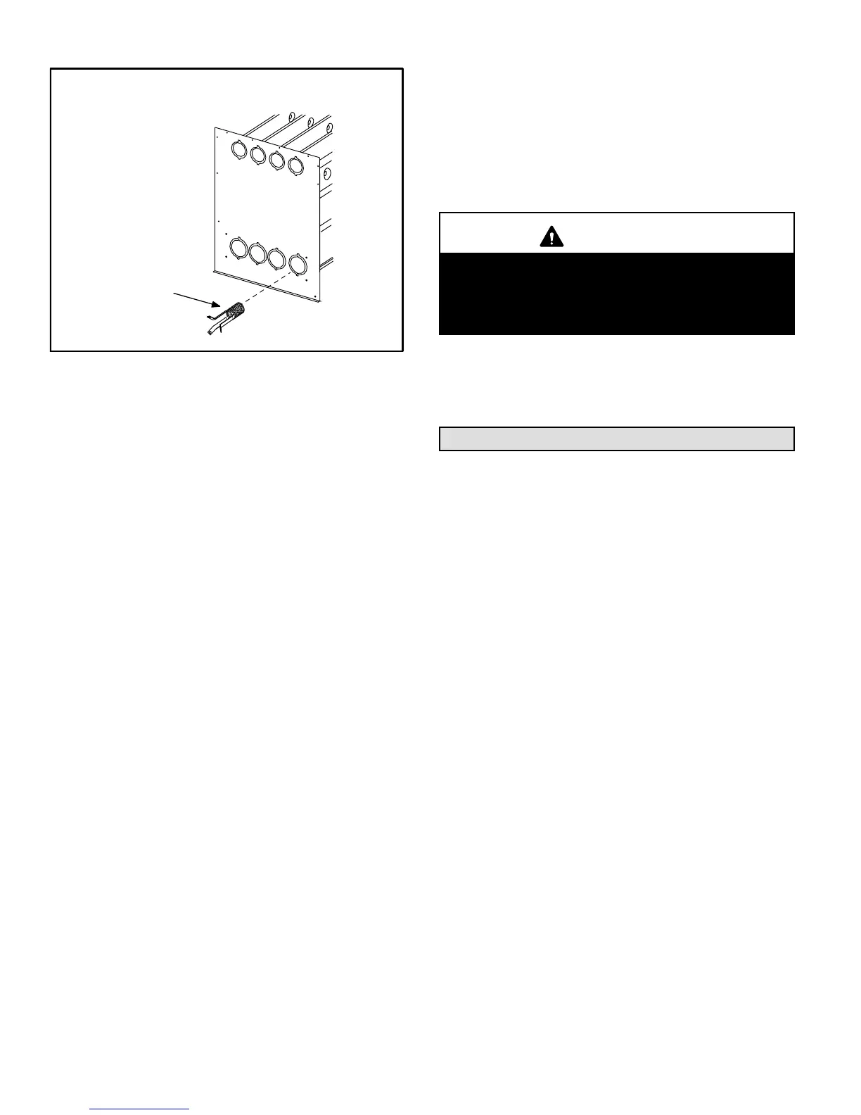
8 − Insert the brush end of cable snake into the top of one
of the heat exchanger openings. Do not force the
cable into the heat exchanger. Insert the cable and
operate the drill on slow speed. Move the cable in and
out of the heat exchanger section three or four times or
until sufficient cleaning is accomplished. Reverse drill
and slowly work the cable out of opening.
9− Repeat procedure for each heat exchanger section.
10− After each of the top heat exchanger sections has been
cleaned, insert the brush end of the cable snake into
the bottom openings of each of the heat exchanger
sections and clean as described in step 8.
11− Remove the cable from the heat exchanger. Use a vac-
uum cleaner to remove debris knocked loose during
cleaning.
12− Attach the exhaust end (positive pressure) of the vacu-
um cleaner to the top of the heat exchanger section.
Any loose debris will be forced to the bottom of the heat
exchanger section. Vacuum debris from bottom open-
ings.
13− Replace collector box and combustion air inducer.
Check gaskets for damage. Damaged gaskets must
be replaced to avoid heat exchanger leaks. Replace all
screws to the collector box and combustion air inducer.
Failure to replace all screws may cause leaks.
14− To clean the burner, run a vacuum cleaner with a soft
brush attachment over the face of burners. Visually in-
spect inside the burners and crossovers for any block-
age caused by foreign matter. Remove any blockage.
15− NOx Units − Reattach the NOx inserts to the corbels at
the entrance to each heat exchanger opening. See fig-
ure 31.
16− Replace burner/manifold assembly onto the vestibule
panel.
17− Reconnect wires to pressure switch, roll−out switches,
gas valve and combustion air inducer. Refer to unit wir-
ing diagram.
18− Reconnect vent pipe to combustion air inducer outlet.
19− Reconnect gas supply piping.
20− Turn on power and gas supply to unit.
21− Set thermostat and check for proper operation.
22− Check all piping connections, factory and field, for gas
leaks. Use a leak detecting solution or other preferred
means.
CAUTION
Some soaps used for leak detection are corrosive to
certain metals. Carefully rinse piping thoroughly af-
ter leak test has been completed. Do not use
matches, candles, flame or other sources of ignition
to check for gas leaks.
23− If a leak is detected, shut gas and electricity off and re-
pair leak.
24− Repeat steps 23 and 24 until no leaks are detected.
25− Replace front access panel.
Planned Service
The service technician should check the following during
an annual inspection. Power to the unit must be shut off for
the service technician’s safety.
Fresh air grilles and louvers (on the unit and in the room
where the furnace is installed) − Must be open and unob-
structed to provide combustion air.
Burners − Must be inspected for rust, dirt, or signs of water.
Vent pipe − Must be inspected for signs of water, damaged
or sagging pipe, or disconnected joints.
Unit appearance − Must be inspected for rust, dirt, signs
of water, burnt or damaged wires, or components.
Blower access door − Must be properly in place and pro-
vide a seal between the return air and the room where the
furnace is installed.
Return air duct − Must be properly attached and provide
an air seal to the unit.
Operating performance − Unit must be observed during
operation to monitor proper performance of the unit and the
vent system.
Combustion gases − Flue products must be analyzed and
compared to the unit specifications.
Problems detected during the inspection may make it nec-
essary to temporarily shut down the furnace until the items
can be repaired or replaced.
Instruct the homeowners to pay attention to their fur-
nace. Situations can arise between annual furnace inspec-
tions that may result in unsafe operation.
 Loading...