Page 10
WARNING
Shock hazard.
Disconnect power before servicing. Control is
not field repairable. If control is inoperable, sim-
ply replace entire control.
Can cause injury or death. Unsafe operation will
result if repair is attempted.
4. SureLight
®
Integrated Ignition Control
97L48 (A92)
ALL −1 units and 090−2 units
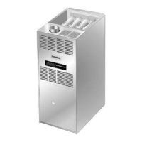
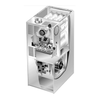
The SureLight hot surface ignition system consists of inte-
grated ignition control (figure 6 with control terminal desig-
nations in table 3), hot surface ignitor (figure 9) and sensor
(figure 10). The ignition control and ignitor work in com-
bination to ensure furnace ignition and ignitor durability.
The ignition control, controls all major furnace operations.
The ignition control also features two green LED lights
(DIAG 1 and DIAG 2) for troubleshooting and two accesso-
ry terminals each rated at (1) one amp. Tables 1 and 2 show
jack plug terminal designations. See table 8 for trouble-
shooting diagnostic codes. Units equipped with the Sur-
eLight hot surface ignition system can be used with either
electronic or electro−mechanical thermostats without mod-
ification. The ignitor is made of durable silicon−nitride. Igni-
tor longevity is also enhanced by voltage ramping by the
ignition control. The ignition control finds the lowest ignitor
temperature which will successfully light the burner, thus
increasing the life of the ignitor. Each time power is applied
to the furnace, the ignition control performs a self check in-
cluding energizing the combustion air inducer for a period
of 1 second.
a−Electronic Ignition (See Figure 7)
On a call for heat the ignition control monitors the combus-
tion air inducer prove switches. The ignition control will not
begin the heating cycle if the prove switch is closed (by−
passed). Once the proving switch is determined to be open,
the combustion air inducer is energized. When the differen-
tial in the prove switch is great enough, the prove switch
closes and a 15−second pre−purge begins. If the prove
switch is not proven within 2−1/2 minutes, the control goes
into Watchguard−Pressure Switch mode for a 5−minute re−
set period.
After the 15−second pre−purge period, the ignitor warms up
for 20 seconds then the gas valve opens for a 4−second trial
for ignition. The ignitor is energized during the 4−second
ignition trial until flame is sensed. If ignition is not proven
during the 4−second period, the ignition control will try four
more times with an inter purge and warm−up time between
trials of 35 seconds. After a total of five trials for ignition (in-
cluding the initial trial), the ignition control goes into Watch-
guard−Flame Failure mode. After a 60−minute reset period,
the ignition control will begin the ignition sequence again.
TABLE 1
IGNITION CONTROL 97L48 J156 TERMINAL
DESIGNATIONS
PIN # FUNCTION
1 Ignitor
2
Not Used
3
Ignitor Neutral
4
Combustion Air Inducer Line Voltage
5
Not Used
6
Combustion Air Inducer Neutral
TABLE 2
IGNITION CONTROL 97L48 J58 TERMINAL
DESIGNATIONS
PIN # FUNCTION
1 Primary Limit In
2
Gas Valve Common
3
Roll Out Switch Out
4
Gas Valve 24V
5
Pressure Switch In
6
Pressure Switch and Primary Limit Out
7
Not Used
8
Roll Out Switch In
9
Ground
The ignition control has an added feature that prolongs the
life of the ignitor. After a successful ignition, the ignition con-
trol utilizes less power to energize the ignitor on successive
calls for heat. The ignition control continues to ramp down
the voltage to the ignitor until it finds the lowest amount of
power that will provide a successful ignition. This amount of
power is used for 255 cycles. On the 256th call for heat, the
ignition control will again ramp down until the lowest power
is determined and the cycle begins again.
b−Fan Time Control
The fan on time of 45 seconds is not adjustable. Fan off time
(time that the blower operates after the heat demand has
been satisfied) can be adjusted by setting the dip switches
located on the ignition control board. The unit is shipped
with a factory fan off setting of 90 seconds. Fan off time will
affect comfort and is adjustable to satisfy individual applica-
tions. For customized comfort, monitor the supply air tem-
perature once the heat demand is satisfied. Note the supply
air temperature at the instant the blower is de−energized.
Adjust the fan−off delay to achieve a supply air temperature
between 90°F − 110°F at the instant the blower is de−ener-
gized. (Longer delay times allow for lower air temperature,
shorter delay times allow for higher air temperature). See
figure 5.
 Loading...