Page 9
I−UNIT COMPONENTS
G51MP unit components are shown in figure 1. The com-
bustion air inducer, gas valve and burners can be accessed
by removing the burner access panel. The blower and con-
trol box can be accessed by removing the blower access
door. G51MP units are designed for bottom and side re-
turn air.
CAUTION
Electrostatic discharge can affect electronic
components. Take precautions during furnace
installation and service to protect the furnace’s
electronic controls. Precautions will help to avoid
control exposure to electrostatic discharge by
putting the furnace, the control and the techni-
cian at the same electrostatic potential. Neutral-
ize electrostatic charge by touching hand and all
tools on an unpainted unit surface, such as the
gas valve or blower deck, before performing any
service procedure.
ELECTROSTATIC DISCHARGE (ESD)
Precautions and Procedures
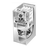
A−Make-Up Box (Figure 2)
A field make-up box is provided for line voltage wiring. Line
voltage wiring to unit is routed from the make up box. The hot"
wire is connected to the door switch and then from the switch
to the ignition control. The make−up box may be installed inside
or outside the unit and on the unit left or right side (right side
shown figure 2).
FIGURE 2
INTERIOR MAKE−UP BOX INSTALLATION
MAKE−UP
BOX
Right Side
CLAMP LOCATION
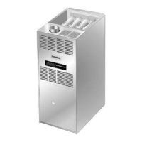
B−Control Box Components (Figure 3)
Unit transformer (T1), igntion control (A92) and circuit
breaker (CB8) are located in the control box. In addition, a
door interlock switch (S51) is located in the control box.
FIGURE 3
DOOR INTERLOCK
SWITCH (S51)
IGNITION
CONTROL
(A92)
TRANSFORMER
(T1)
CIRCUIT BREAKER
(CB8)
1. Transformer (T1)
A transformer located in the control box provides power to
the low voltage section of the unit. The transformers on all
models are rated at 40VA with a 120V primary and 24V
secondary.
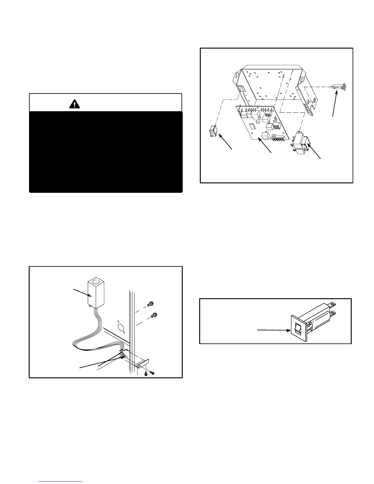
2. Circuit Breaker (CB8)
A 24V circuit breaker is also located in the control box. The
switch provides overcurrent protection to the transformer
(T1). The breaker is rated at 3A at 32V. If the current ex-
ceeds this limit the breaker will trip and all unit operation
will shutdown. The breaker can be manually reset by
pressing the button on the face. See figure 4.
FIGURE 4
CIRCUIT BREAKER CB8
PRESS TO RESET
3. Door Interlock Switch (S51)
A door interlock switch rated 14A at 120VAC is located on
the control box. The switch is wired in series with line volt-
age. When the blower door is removed the unit will shut
down.
 Loading...