Page 4
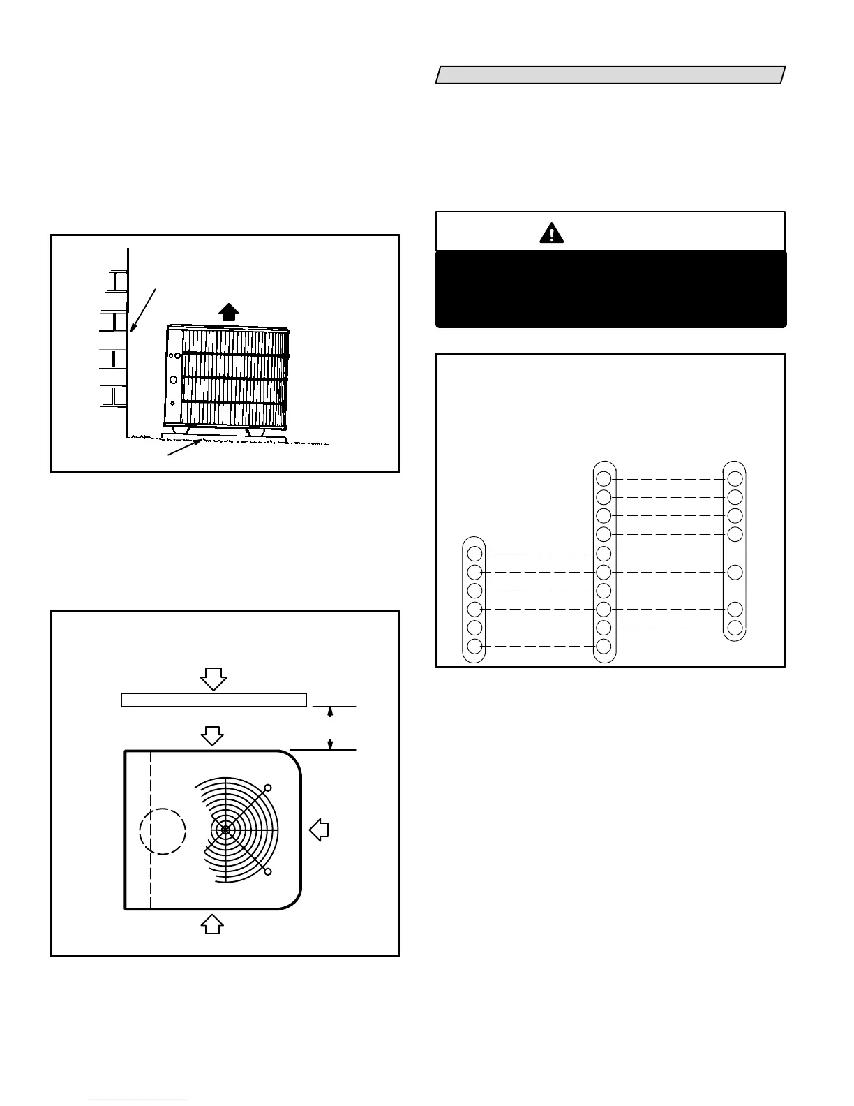
Slab Mounting (See figure 3)
When installing unit at grade level, top of slab should
be high enough above the grade so that water from
higher ground will not collect around unit. Slab should
have a slope tolerance away from the building of 2 de
grees or 2 inches per 5 feet (51mm per 1.5m). This will
prevent ice build-up under unit during a defrost cycle.
Refer to roof mounting section for barrier construction
if unit must face prevailing winter winds.
2 DEGREES or 2 IN. PER 5 FT.
(51mm per 1.5m)
SLOPE
TOLERANCE AWAY FROM
BUILDING STRUCTURE
BUILDING
STRUCTURE
GROUND LEVEL
MOUNTING SLAB
SLAB MOUNTING
FIGURE 3
DISCHARGE
AIR
Roof Mounting (See figure 4)
If unit coil cannot be mounted away from prevailing
winter winds, a wind barrier should be constructed.
Size barrier at least the same height and width as out
door unit. Mount barrier 24 inches (610mm) from the
sides of the unit in the direction of prevailing winds.
WIND BARRIER
INLET AIR
PREVAILING WINTER WINDS
ROOFTOP APPLICATION
WIND BARRIER CONSTRUCTION
INLET AIR
INLET
AIR
FIGURE 4
24"
(610mm)
ELECTRICAL
Wiring must conform to the National Electric Code
(NEC) and local codes. Application diagram is included
in this instruction (see figure 6) and in indoor unit
instructions. Refer to figure 5 for thermostat designa
tions. Refer to unit rating plate for minimum circuit am
pacity and maximum fuse size.
WARNING
Unit must be grounded in accordance with
national and local codes.
Electric Shock Hazard.
Can cause injury or death.
FIGURE 5
EMERGENCY HEAT
COMMON
POWER
1ST STAGE AUX. HEAT
INDOOR BLOWER
T
L
O
Y1
E
C
W2
R
W1
G
2ND STAGE AUX. HEAT
E
C
W2
R
W1
G
AMBIENT SENSOR
SERVICE LIGHT
REVERSING VALVE
COMPRESSOR
COMMON
POWER
DEFROST SENSING/
1ST STAGE AUX. HEAT
T
L
O
Y1
C
R
W1
HP25 and BLOWER UNIT
THERMOSTAT DESIGNATIONS
(WITH OR WITHOUT AUXILIARY HEAT)
(Some connections may not apply.
Refer to specific thermostat and indoor unit.)
HP25ThermostatIndoor
Blower
Unit
1- Provide line voltage power supply to unit from a
properly sized disconnect switch. See figure 6.
2- Install room thermostat (ordered separately) in
the conditioned area. Locate where it will not be
affected by sunlight, drafts or vibration. Do not
install on an outside wall. A position approxi
mately 5 feet (1.5m) from the floor and near the
center of the conditioned area is most desirable.
3- Provide low voltage wiring from outdoor to indoor
unit and from thermostat to indoor unit as indi
cated on the field wiring diagram in this instruc
tion. See figure 6.
4- Ground unit either through supply wiring or with
an earth ground.
 Loading...
