Page 3
ELECTRICAL DATA
Model No. HP29-018 HP29-024 HP29-030 HP29-036
Line voltage data 60 hz
208/230v
1ph
208/230v
1ph
208/230v
1ph
208/230v
1ph
208/230v
3ph
460v
3ph
Rated load amps 7.9 10.1 14.7 16.0 11.0 5.6
Compressor Power factor .97 .96 .90 .91 .83 .83
Locked rotor amps 49.0 60.0 84.0 100 75.0 37.5
Outdoor Coil
Full load amps 1.1 1.1 1.1 1.1 1.1 0.55
Fan Motor
Locked rotor amps 1.9 1.9 1.9 1.9 1.9 1.0
Rec. maximum fuse or circuit breaker size (amps) 15 20 30 35 20 10
*Minimum circuit ampacity 11.0 13.8 19.5 21.1 14.0 6.5
*Refer to National or Canadian Electrical Code manual to determine wire, fuse and disconnect size requirements.
NOTE Extremes of operating range are plus 10% and minus 5% of line voltage.
ELECTRICAL DATA
Model No. HP29-042 HP29-048 HP29-060
Line voltage data 60 hz
208/230v
1ph
208/230v
3ph
460v
3ph
208/230v
1ph
208/230v
3ph
460v
3ph
575v
3ph
208/230v
1ph
208/230v
3ph
460v
3ph
575v
3ph
Rated load amps 20.3 12.8 6.4 23.7 13.5 7.4 5.8 28.8 17.3 9.0 7.1
Compressor Power factor .84 .93 .93 .96 .88 .88 .88 .92 .86 .86 .86
Locked rotor amps 127 87.0 44.0 129.0 120.0 49.5 48.0 169.0 137.0 62.0 51.0
Outdoor Coil
Full load amps 1.9 1.1 0.55 1.9 1.9 0.90 0.90 1.9 1.9 0.90 0.90
Fan Motor
Locked rotor amps 4.1 1.9 1.0 4.1 4.1 2.1 2.1 4.1 4.1 2.1 2.1
Rec. maximum fuse or circuit breaker size (amps) 40 25 15 50 30 15 10 60 40 20 15
*Minimum circuit ampacity 27.3 17.1 8.6 31.5 18.8 10.2 8.2 37.4 23.5 12.2 9.8
*Refer to National or Canadian Electrical Code manual to determine wire, fuse and disconnect size requirements.
NOTE Extremes of operating range are plus 10% and minus 5% of line voltage.
I − UNIT INFORMATION
HP29 units are available in 1 -1/2, 2, 2 -1/2, 3, 3 -1/2, 4 and 5
ton capacities.
All major components (indoor blower/coil) must be matched
according to Lennox recommendations for the compressor to
be covered under warranty. Refer to the Engineering
Handbook for approved system matchups. A misapplied
system will cause erratic operation and can result in early
compressor failure.
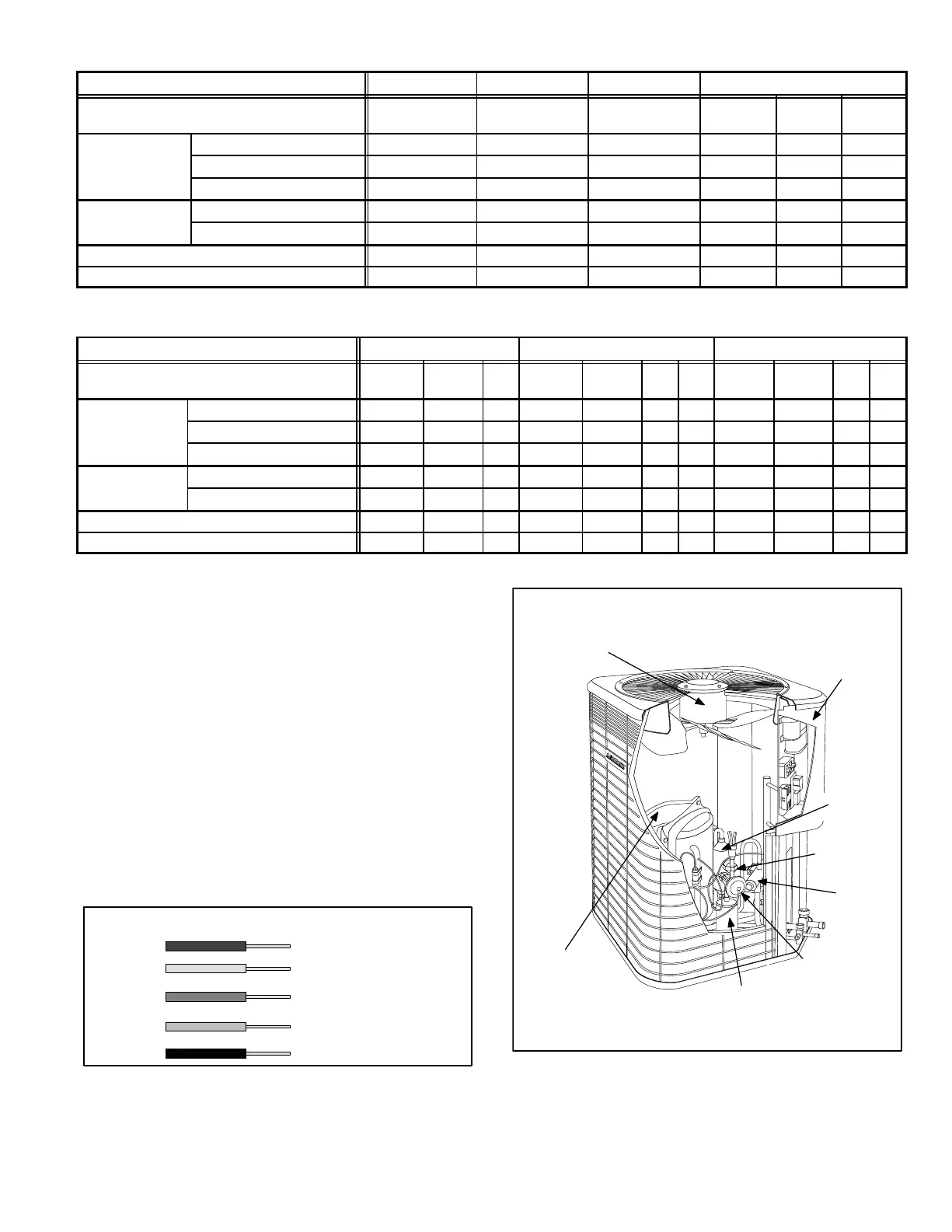
II − UNIT COMPONENTS
Unit components are illustrated in figure 2.
A − Control Box (Figures 3, 4 and 5)
Electrical openings are provided under the control box
cover. Field thermostat wiring is made to color-coded
pigtail connections as illustrated in figure 1.
FIGURE 1
THERMOSTAT WIRING IDENTIFICATION
BLACK
BEIG
E
ORANGE
YELLOW
RED
FROM OUTDOOR UNIT
TO INDOOR UNIT/
THERMOSTAT
24V (POWER) INPUT
TO OUTDOOR UNIT
(COMPRESSOR)
(REVERSINGVALVE)
(ELECTRIC
HEAT)
(COMMON)
INPUT
INPUT
DEFROST OUTPUT
COMPRESSOR
CHECK/EXPANSION
VALVE
CONTROL
BOX
REVERSING
VALVE
DISCHARGE
MUFFLER
OUTDOOR
FAN/MOTOR
HP29 UNIT COMPONENTS
FIGURE 2
DEFROST
THERMOSTAT
BI-FLOW
FILTER DRIER
RECIPROCATING COMPRESSOR
SHOWN
 Loading...
