Page 3
1 - Compressor Contactor K1
The compressor is energized by a contactor located in the
control box. See figures 1 and 2. Contactors are SPST in
single phase units and 3PST in three phase units. The conĆ
tactor is energized by indoor thermostat terminal Y when
thermostat demand is present.
The contactor coil is energized by 24VAC supplied by the
indoor unit. All other controls in the outdoor unit are powĆ
ered by line voltage. Refer to unit wiring diagram. The
HS24 is not equipped with a line voltage to 24V transformĆ
er.
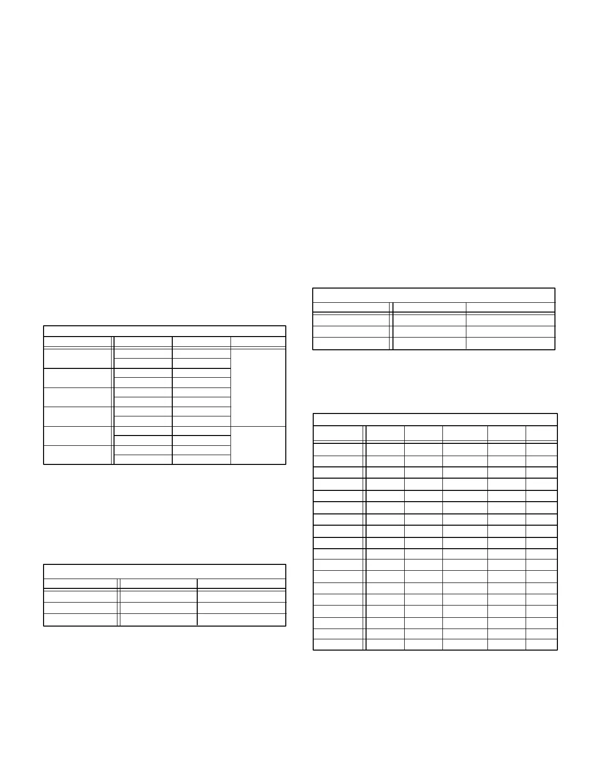
2 - Dual Capacitor C12
The compressor and fan in single phase units use permanent
split capacitor motors. The capacitor is located inside the unit
control box (see figure 1). A single dual" capacitor (C12) is
used for both the fan motor and the compressor (see unit wirĆ
ing diagram). The fan side and the compressor side of the caĆ
pacitor have different MFD ratings. See table 1 for dual capacĆ
itor ratings.
TABLE 1
Unit MFD VAC
HS24 (C12) DUAL CAPACITOR RATING
HS24-261
HS24-311/411
HS24-461
HS24-511
5
30
5
45
5
370
10
50
45
Terminal
FAN
HERM
FAN
HERM
FAN
HERM
FAN
HERM
440
HS24-141/211
5
25
FAN
HERM
HS24-651
10
60
FAN
HERM
3 - Start Capacitor C7
All HS24-461, 511, 651 units use a start capacitor (C7) wired
in parallel with the compressor side of the dual capacitor. The
capacitor is located inside the unit control box (see figure 1).
C7 is switched off by potential relay (K31) when the compresĆ
sor nears full speed.ĂSee table 2 for startĂcapacitor ratings.
TABLE 2
Unit MFD VAC
HS24 START CAPACITOR RATING
HS24-461
HS24-511
189-227
HS24-651
330
189-227 330
135-155 320
4 - Transformer T5
Transformer T5 is used on all J" voltage units. T5 is used as
a stepĆdown transformer for fan B4. T5 is rated at 3.4 VA with
a 575 volt primary and a 460 volt secondary.
5 - Potential (Start) Relay K31
All HS24-461, 511, 651 series units use a potential relay
which controls the operation of the starting circuit. The poĆ
tential relay is located inside the unit control box (see figure
1). The relay is normally closed when contactor K2 is deĆenĆ
ergized. When K1 energizes, the compressor immediately
begins startĆup. K31 remains closed during compressor
startĆup and the start capacitor remains in the circuit. As the
compressor gains speed, K31 is energized. When K31 enĆ
ergizes, the contacts open and the start capacitor is taken
out of the circuit.
6 - Fan Capacitor C1
The fan in threeĆphase units use permanent split capacitor
motors. A single capacitor is used for the fan motor. The caĆ
pacitor is located inside the unit control box (see figure 2).
Table 3 shows the ratings of C1.
TABLE 3
Unit MFD VAC
HS24 FAN CAPACITOR RATING (C1)
HS24-413/463
HS24-513/653Y,G
HS24-651J
10 370
10 370
5 370
B - Compressor
Table 4 shows the specifications of compressors used in
HS24 series units.
TABLE 4
Unit Phase LRA RLA
Oil
fl.oz.
HS24-211
HS24-311
HS24-511
1
1
1
49
71.0
110
32*
54*
45*
**Shipped with 60% Zerol 300Ċ40% Sontex 200LT. A 60/40 mixture of
Zerol 300/Sontex 200LT may be used if additional oil is required.
9.6
11.7
20.5
HS24-141 1 26.3 4.8
HS24-413 3 32.8 54*4.6
HS24-651 1 147 24 65*
15**
HS24-653
HS24-653
3
3
150
73
65*
65*
16
8.0
HS24-463 3 130 70*11.9
460
HS24-413 3 65.1 54*9.2
208/230
HS24-653 3 50.0 6.4 65*
HS24-461 1 105 70*16.4
HS24-411 1 86.7 54*14.2
HS24-261 1 56 45*10.9
HS24-463 3 64 70*5.6
HS24-513 3 92.0 54*13.4
HS24-513 3 46.0 54*6.7
HS24-513
Voltage
208/230
208/230
208/230
208/230
208/230
208/230
208/230
208/230
208/230
208/230
208/230
460
460
460
575
575
HS24 COMPRESSOR SPECIFICATIONS
3 44.0 54*5.3
*Shipped with conventional white oil (Sontex 200LT) or 3GS. 3GS oil may
be used if additional oil is required.
 Loading...