Page 5
D–Compressor
Table 1 shows the specifications of compressors used
in HS25 series units.
TABLE 1
Unit Phase LRA RLA
Oil
fl.oz.
HS25–261
HS25–311
HS25–411
HS25–461
1
1
1
1
62.5
76.0
90.5
107
28*
34*
38*
28*
*Shipped with conventional white oil (Sontex 200LT). 3GS oil
may be used if additional oil is required.
11.6
13.5
18.0
20.0
HS25–211 1 50.0 9.7 24*
HS25–511
HS25–651
1
1
129
169
52*
54*
23.7
28.8
E–Temperature Sensor
Scroll compressors up to 3-1/2 tons are equipped with
a temperature sensor located on the outside top of the
compressor. The sensor is a SPST thermostat which
opens when the discharge temperature exceeds 280F
+ 8F on a temperature rise. When the switch opens,
the circuit to the compressor contactor and the time
delay is de–energized and the unit shuts off. The switch
automatically resets when the compressor tempera-
ture drops below 130F + 14F.
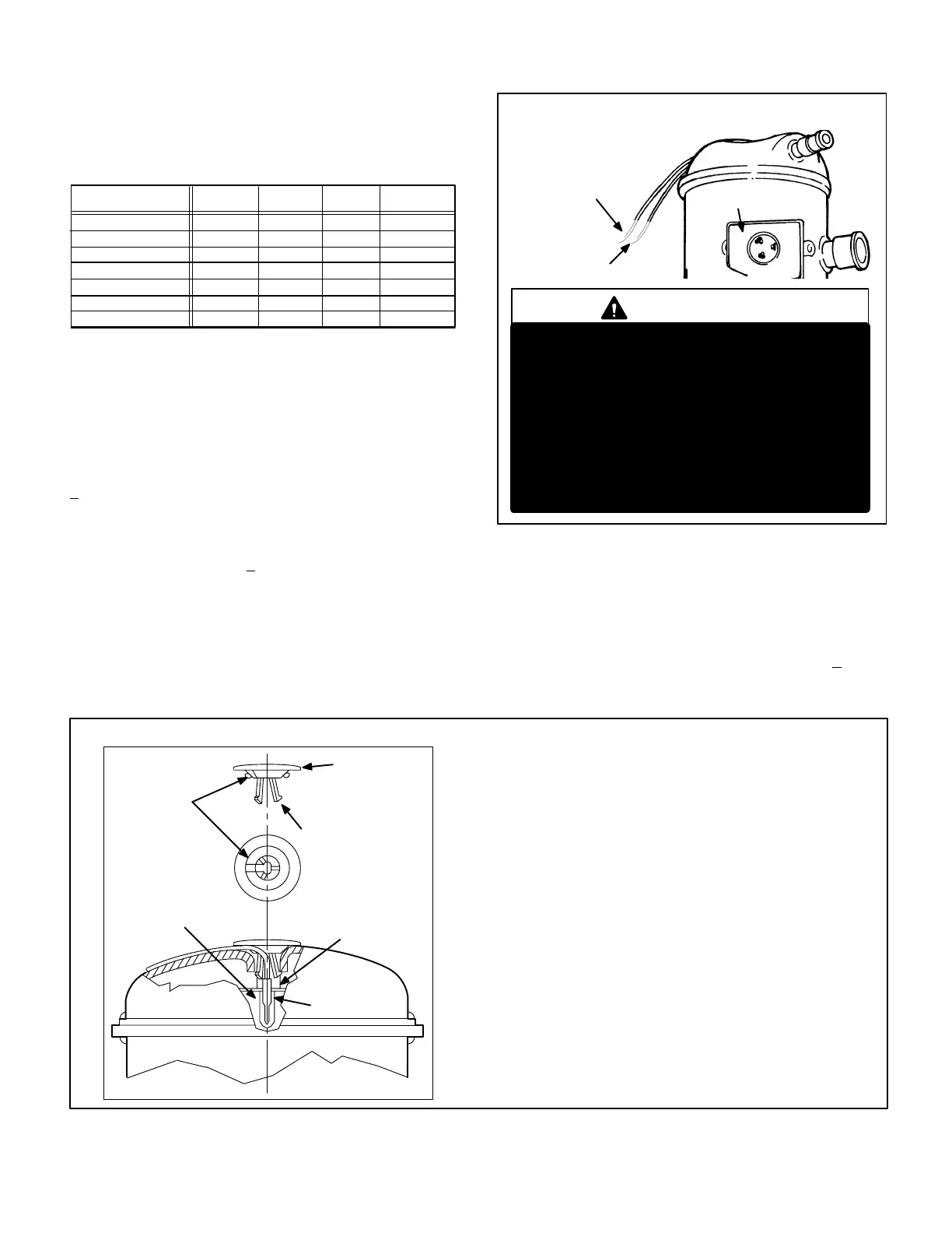
The sensor can be accessed by prying off the snap plug
on top of the compressor (see figure 6). Make sure to
securely seal the sensor after replacement. The sensor
pigtails are located inside the unit control box. Figure 5
shows the arrangement of compressor line voltage
terminals and discharge sensor pigtails.
COMPRESSOR TERMINAL BOX
C
S
R
COMPRESSOR
TERMINALS
FIGURE 5
WARNING
COMPRESSOR MUST BE GROUNDED. DO
NOT OPERATE WITHOUT PROTECTIVE COVER
OVER TERMINALS. DISCONNECT ALL POWER
BEFORE REMOVING PROTECTIVE COVER.
DISCHARGE CAPACITORS BEFORE SERVICING
UNIT. COMPRESSOR WIRING DIAGRAM IS
FURNISHED INSIDE COMPRESSOR TERMINAL
BOX COVER. FAILURE TO FOLLOW THESE
PRECAUTIONS COULD CAUSE ELECTRICAL
SHOCK RESULTING IN INJURY OR DEATH.
DISCHARGE TEMPERATURE
SENSOR WIRES
TO CONTROL BOX
(TO COMP. TERM. BOX IN
-461 UNITS)
3-1/2 TON
AND SMALLER ONLY
F–High Pressure Switch
A manual-reset single-pole single-throw high pressure
switch located in the discharge line of the compressor
shuts off the compressor when discharge pressure rises
above the factory setting. The switch is normally closed
and is permanently adjusted to trip (open) at 410 + 10 psi.
See figure 4 for reset switch location.
FIGURE 6
SCROLL HIGH TEMPERATURE LIMIT CHANGEOUT (3-1/2 ton and smaller only)
Instructions
1- With power off, disconnect wiring to limit.
2- Dislodge limit/cap assembly from compressor. Plastic cap and sili-
cone seal will break away. Discard all pieces.
3- Remove thermostat and grommet from compressor. Thoroughly
clean all blue adhesive and white silicone thermal grease from com-
pressor and the inside of the thermostat tube. Thermostat tube should
be clean and free of debris.
4- Using Lennox kit 93G8601, dip end of thermostat into plastic bottle la-
beled “Silicone Thermal Grease G.E. #G641” and coat end of thermo-
stat. Carefully insert thermostat/grommet assembly into thermostat
tube of compressor. Avoid contact with top of compressor.
5- Clean excess thermal grease from under cap lip and top lip of com-
pressor opening.
6- Install protector assembly as shown, feeding wire leads through
channel provided in cap.
7- Apply a bead of sealant around lip of cap at area shown in illustration
and into the thermostat tube area.
8- Install assembly as shown. Align wires to channel in compressor
shell. Sufficient force is required to snap plastic cap into tube to en-
gage all three prongs.
9- Re-connect wiring.
10-After completing thermostat replacement, discard remaining parts.
PLASTIC CAP
PRONG
GROMMET
SEALANT
(BLUE)
COMPRESSOR
THERMAL GREASE
(WHITE)
LIMIT
(THERMOSTAT)
 Loading...